
Question 2
AIM: To investigate the voltage regulation of the full-wave rectifier circuit.
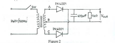
- Connect the circuit diagram as shown in Figure 2.
- Ask the supervisor to check the circuit connection.
- Copy Table2 into your answer booklet.
Table 2
Input voltage (V) a.c |
Output voltage |
Percentage voltage regulation |
|||||
VAB |
VBC |
VAC |
RL= 1kΩ |
RL=47 Ω |
RL(removed) |
RL= 1kΩ |
RL= 47 Ω |
|
|
|
|
|
|
|
|
- Close switch (sw).
- Measure and record in Table 2, the voltages VAB, VBC and VAC.
- Open switch (sw) and replace the 1 kΩ resistorwith 47 Ω resistor.
- Repeat steps (d) to (e).
- Open switch (sw) and remove the 47 Ω resistor.
- Repeat steps (d) and (e) for no resistor in the circuit diagram.
- Open switch (sw).
- Using the formulae in Experiment 1, step (k), calculate the percentage voltage regulation for the (i) 1 kΩ resistor; (ii) 47 Ω resistor.
- Which of the two rectifier circuits has a better percentage voltage regulation? The candidates were expected to connect the circuit as shown, measure and record the values of the voltmeter, calculate percentage voltage regulation and compare the results of the two experiments.
Observation
The expected answers were:
Table 2
Input Voltage (V) a.c. |
Output Voltage (V)(out)d.c |
Percentage Voltage Regulation |
|||||
VAB |
VBC |
VAC |
RL = 1K Ω |
RL = 47 Ω |
RL (removed) |
RL =1K Ω |
RL= 47Ω |
8.5V |
8.5V |
16.8V |
10.1V |
8.88V |
12.00V |
19.00V |
35.10V |
(k) (i) RL =1K Ω 15.7% - Half wave - better regulation 19.0% - Full wave
(ii) RL = 47 Ω 58.8% - Half wave 25.1% - Full wave - better regulation