Question 2
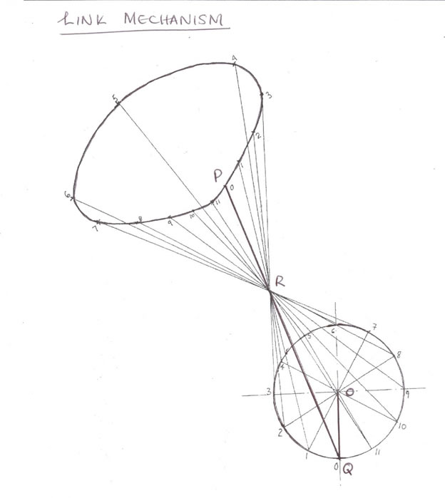
(2) The figure above shows crank OQ which rotates in clockwise direction. The rod PQ is connected to the crank at Q and slides through the slot R.
Plot, full size, the locus of point P when the crank makes one revolution.
Observation
Candidates were expected to:
- copy the given mechanism (crank OQ, Circle R25, Rod QP, Slot R, Centre lines);
- divide circle into 8 or 12 equal parts;
- locate different positions of rod QP;
- mark different positions of point P;
- join points P into a curve;
- use correct scale and positioning;
- draw neatly.
The solution is shown below: