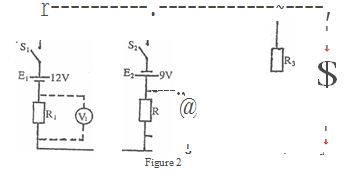
(a) Connect the circuit as shown in Fig.2.
(b) Ask the Supervisor to check the circuit.
(c) Copy Table 2 .
Table 3
|
Vl(v) |
V2(v) |
V3(v) |
Voltmeter reading |
|
|
|
(d) Close the switches Sl and S2'
(e) Measure, read and record in Table 2 the voltage drop across Rl.
(f) Repeat step (e) for R2 and R3•
(g) Evaluate El + VI'
(h) Evaluate E2 + V2.
(i) Compare the values obtained in steps (g) and (h) with V3.
(j) What is your conclusion?
(k) Evaluate:
(i) El + E2;
(ii) VI + V2•
(I) Comment on your results in (k).
(m) Which law does your result in (k) obey?


