Question 6
- Table 5contains some indicators on a car dashboard.
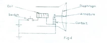
- Fig. 4 is the circuit diagram of a motor vehicle horn.
Table 5
|
Indicator |
Quantity measured |
Unit of measurement |
(i) |
Speedometer |
|
|
(ii) |
Tachometer |
|
|
(iii) |
Odometer |
|
|
Complete Table 5.
List five warning lights on the dashboard of a motor vehicle.

Highlight in four steps, the principle of operation of the horn, starting from the push of
the switch.
Observation
- The candidates were expected to copy and complete the table.
- Warning lights on the dashboard of a motor vehicle
- Seat belt warning light/reminder
- Engine warning light
- Tyre pressure warning light
- Oil pressure warning light
- Traction control warning light
- Engine temperature warning light
- Anti-lock brake warning light
- Automatic shift lock/engine start indicator
- Battery alert
- Fuel indicator symbol
- Air bag indicator
- Fog lamp indicator
- Security light
- Washer fluid indicator
- Highlight of the principle of operation of a motor vehicle horn
Table 5
|
Indicator |
Quantity measured |
Unit of measurement |
(i) |
Speedometer |
Instantaneous speed of vehicle |
Kilometer per hour/ |
(ii) |
Tachometer |
Rotation speed of crank shaft/engine |
Revolution per minute (RPM) |
(iii) |
Odometer |
Distance travelled by a vehicle |
Kilometer/Mile |
- When the switch is pushed, current flows through the coil and the circuit
making the horn to honk
- The coil becomes an electromagnet and attracts the iron at the contact
- The contact breaks and the honking stops
- The make and break is repeated for as long as the switch is pushed.
As reported by Chief Examiner, majority of the candidates that attempted question 6 responded very well to the principle of operation of the horn while responses to other tasks were only fairly good.
