
Question 2
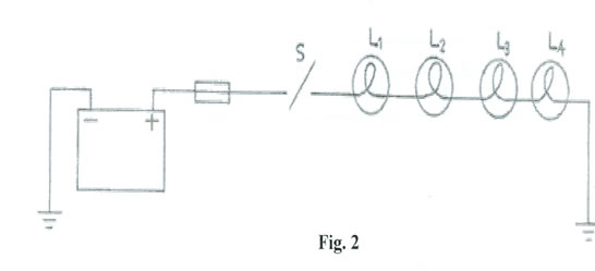
(a) Connect the circuit as shown in Fig. 2.
(b) Copy Table 2 into your answer booklet.
Table 2
Task |
Reading |
Battery voltage on load (switch closed) |
|
Battery voltage off (switch opened) |
|
Voltage across lamp 1 |
|
Voltage across lamp 2 |
|
Voltage across lamp 3 |
|
Voltage across lamp 4 |
|
(c) Measure and record in Table 2 the battery terminal voltage when switch S is opened
(d) Close switch S.
(e) Measure and record the in Table 2 the battery terminal voltage when switch S is closed.
(f) With the switch still closed, measure the voltage drop across lamp 1, lamp 2, lamp 3 and lamp 4 and record your readings in Table 2.
(g) Remove lamp 2 and record the state of other lamps
(h) Why is it that connecting two or more lamps in series is not desirable in auto circuitry?
Observation
The expected answers were;
(a) Copying of the Table correctly into the answer booklet
Table 2
Task |
Reading |
Battery voltage on load (switch closed) |
12V |
Battery voltage on load (switch opened) |
Between 0V – 12V |
Voltage across lamp 1 |
1V |
Voltage across lamp 2 |
2V |
Voltage across lamp 3 |
3V |
Voltage across lamp 4 |
4V |
(b) Battery terminal voltage reading when switch is open (0V – 12V)
(c) battery terminal voltage reading when switch is closed (12V)
(d) voltage across each lamp ( lamp 1=1V, lamp 2 =2V, lamp 3=3V, and lamp 4=4V)
(e) The remaining lamps will go off
(f) Because when one of the lamp blows, the rest will go off
The candidates were required to determine the terminal voltage of a battery on load and no load, voltage drop across four lamps connected in series.
The performance was reported to be averagely good.