|
Question 2
|
Question 2
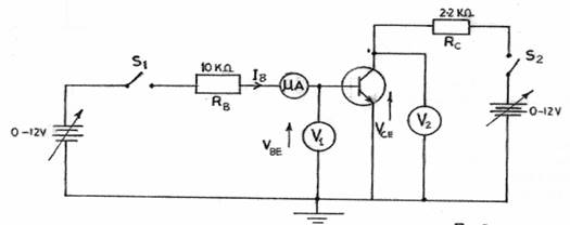
AIM: To determine the input characteristics of a transistor in common emitter configuration.

- Connect the circuit as shown in Fig. 2.
- Ask the supervisor to check the circuit connection.
- Copy Table 2 into your answer booklet.
Table 2
IB ( |
VBE (V) |
10 |
|
20 |
|
30 |
|
40 |
|
50 |
|
60 |
|
- Close switches S1 and S2.
- Set the collector-emitter voltage (V2) to 3 V.
- Adjust the input voltage (V1) until the ammeter reads 10
 . .
- Measure and record in Table 2, the corresponding base emitter voltage (VBE).
- Repeat steps (f) and (g) for other values of IB in Table 2.
- Open switches S1 and S2.
- Plot a graph of IB (
 on the vertical axis against VBE (V) on the horizontal axis. on the vertical axis against VBE (V) on the horizontal axis.
- Calculate the slope of the graph.
- Comment briefly on the slope of the graph.
The candidates were expected to connect the circuit as shown in Fig. 2, measure and record in Table 2 the expected VBE (V) readings. They were also required to plot a graph of IB ( against VBE (V), calculate the slope and comment briefly on it. against VBE (V), calculate the slope and comment briefly on it.
The expected answers were:
(c) Table 2
IB( ) ) |
VBE(V) |
10 |
0.50 – 0.65 |
20 |
0.50 – 0.65 |
30 |
0.50 – 0.65 |
40 |
0.50 – 0.65 |
50 |
0.50 – 0.65 |
60 |
0.50 – 0.65 |
As reported, majority of the candidates who attempted this question did very well.
|
| _____________________________________________________________________________________________________ |
|
|
|
|
|


