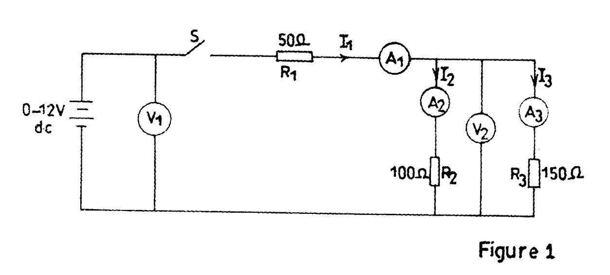
Question 3
-
AIM: To verify Kirchhoff’s Laws.

(a) Connect the circuit as shown in Fig. 1.
(b) Ask the supervisor to check the circuit connection.
(c) Copy Table 3 into your answer booklet.
Table 3
I1(mA)
V1(V)
I2(mA)
I3(mA)
V2(V)
I1R1
I2 R2
I3 R3
50
100
(d) Close switch S.
(e) Vary the battery voltage to set current I1 to 50mA.
(f) Read and record in Table 3 the values of I2, I3, V1 and V2.
(g)Repeat steps (e) and (f) for I1 set to 100mA.
(h) Using the readings recorded in Table 3, calculate the potential difference across R1,
R2 and R3 and record as I1R1,I2R2 and I3R3 respectively.
(i) Compare I2R2and I3R3 with V2.
(j) From the results recorded in Table 3, show whether or not the following laws are
justified:- Kirchhoff’s Voltage Law;
- Kirchhoff’s Current Law.
(k) State two precautions taken when carrying out this experiment.
Observation
The candidates were expected to connect the circuit as shown in Fig.1, measure and record in Table 3. And the expected answers were:
- (a)Correct circuit connection
- (c) Table 3 copied correctly
Table 3
I1(mA) |
V1(V) |
I2(mA) |
I3(mA) |
V2(V) |
I1R1 |
I2 R2 |
I3 R3 |
50 |
5.5 |
30.0 |
20.0 |
3.0 |
2.5 |
3.0 |
3.0 |
100 |
11.0 |
60.0 |
40.0 |
6.0 |
5.0 |
6.0 |
6.0 |
- I2R2 and I3R3 are equal/approximately equal to V2.
I2R2 ≈ I3R3 ≈ V2.
(j) Kirchhoff’s Laws Justification
(i) Kirchhoff’s Voltage Law
V1 = I1R1 +I2R2
5.5V = 2.5V + 3.0V OR 11.0V = 6.0V + 5.0V
5.5V = 5.5V 11.0V = 11.0V
- (ii) Kirchhoff’s Current Law
I1 = I2 + I3
50 = 30 + 20 OR 100 = 60 +40
50 = 50 100 = 100
(k) Precautions taken
- I ensured tight connections to avoid sudden disconnection in the course of experiment.
- I ensured correct polarity in the meter connections.
- I avoided dry joints.
Many candidates found it difficult to take correct readings with simple electronic measuring instruments.
