Question 3
AIM: to verify circuit laws.

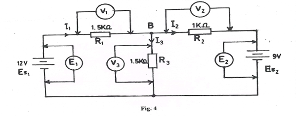
(a) Connect the circuit as shown in Fig. 4.
(b) Ask the supervisor to check the circuit connection.
(c) Switch on the power supply units.
(d) Use the voltmeter to read and record the voltages E1, E2, V1, V2 and V3 in Table 2.
Table 2
|
E1(V) |
E2(V) |
V1(V) |
V2(V) |
V3(V) |
Fig. 4 |
|
|
|
|
|
Fig. 5 |
|
|
|
|
|
(e) Switch off the power supply units
(f) (i) compute V13 = V1 + V3 =
_______________________________
(ii) compare V13 with E1
_______________________________
(g) (i) compute V23 = V2 + V3 =
_______________________________
(ii)compare V23 with E2 =
_________________________________
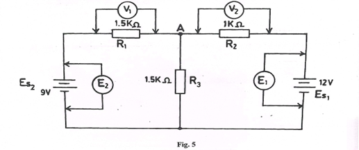
(h) Exchange the sources Es, and Es as shown in Fig. 5

(i) Ask the supervisor to check the connection.
(j) Repeat steps (c) to (e) for the connection in Fig. 5.
(k) (i) compute V13 V1+V3 =
____________________________________
(ii) compare V13 with E2 =
____________________________________
(l) (i) compute V23 = V₂+ V3 =
____________________________________
(ii) compare V23 with E1 =
_______________________________________________________
(m) (i) State the circuit law justified by the results.
________________________________________________________________
(ii) State one reason for your answer in m(i).
________________________________________________________________
(n) State any two precautions taken to ensure accuracy of results.
_________________________________________________________________
Observation
The expected response was:
Table 2
|
E1(V) |
E2(V) |
V1(V) |
V2(V) |
V3(V) |
Fig. 4 |
12.0 |
9.0 |
4.71 |
1.71 |
7.29 |
Fig. 5 |
9.0 |
12.0 |
1.29 |
4.29 |
7.71 |
(Note that negative values indicate reversal of polarity)
From Fig. 4.
(f) (i) V13 = V1 + V3 = 4.71 + 7.29 = 12.0V
- Have the same values. (V13 = E1)
(g) (i) V23 = 1.29 + 7.71 = 9.0V
(ii) V23 = E2 (have equal values)
From Fig.5.
(k) (i) V13 = V1 + V3 = 1.29 + 7.71 = 9.0V
(ii) V13 = E2 (have equal values)
(l) (i) V23 = V2 + V3 = 4.29 + 7.71 = 12.0V
(ii) V23 = E1 (have equal values)
(m) (i) The circuit law justified Kirchoff Voltage Law (KVL)
- Kirchoff Voltage Law states that the algebraic sum of voltages in a closed loop is equal to zero.
- The sum of all voltages around a closed loop in any circuit must be equal to zero.
(ii) Sum of voltage drops is equal to the input voltages i.e. E1 = V1 + V3 and E2 = V2 + V3 in the circuit.
(n)
(i) I ensured tight connections
(ii) I ensured correct polarity of the meter
(iii) I avoided error of parallax in my readings.
(iv) I ensured that the meter is set to the correct voltage range.
The chief examiner reported that the candidates did well in this question.
