Question 5
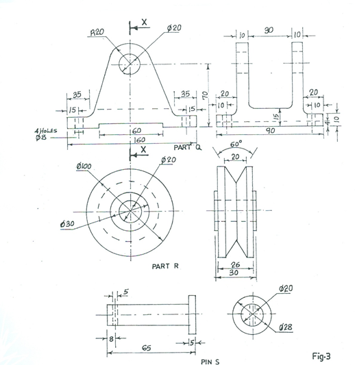
Figure 3 shows the detail of a pulley bracket assembly. Part R is held between the arms of the bracket by the pin S with the point of entry from right to the left.
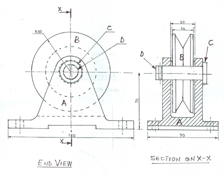
Draw full size, in first angle projection, the following views of the assembled pulley bracket:
(a) end view;
(b) sectional view in the direction of X – X.
Show all hidden details on the front elevation only.

Observation
A detailed pulley bracket assembly was given and candidates were expected to draw full size, in first angle projection the end view, sectional view in the direction of X – X, showing hidden details on the front elevation only.
Very few candidates attempted this question. However, the performance was okay.
Candidates were expected to:
END VIEW
i. draw in first angle projection;
ii draw the outline;
iv. draw (4) centre lines;
v. draw part A in place;
vi. draw part B in place;
vii. draw part C in place;
viii. draw the cutting plane;
ix. draw the end of pin D;
x. show 2 – hidden holes;
xi. show the bottom of vee in hidden;
xii. show the head of pin in hidden;
xiii. show the bottom of groove in part A in hidden.
SECTION ON PLANE X - X
i. draw in first angle projection;
ii draw full size;
iii. draw the outline;
iv. draw (4) centre lines;
v. draw part A (base);
vi. draw part B (pulley;)
vii. draw part C (pin head);
viii. draw part D (pin);
ix. draw pin hole in hidden;
x. show (2) holes in hidden;
xi. section the bracket.

