Question 4
-
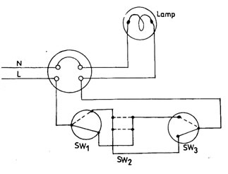
The diagram below shows a circuit consisting of a lamp controlled by three in dependent switches.

(i) Using the diagram, complete the table below.
Switch positionCircuit condition
Lamp condition
SW1
SW2
SW3
Up
Up
Up
Up
Up
Down
Up
Down
Up
Up
Down
Down
Down
Up
Up
Down
Up
Down
Down
Down
Up
(ii) State one precaution to be taken while carrying out the installation in 4(a)(i).
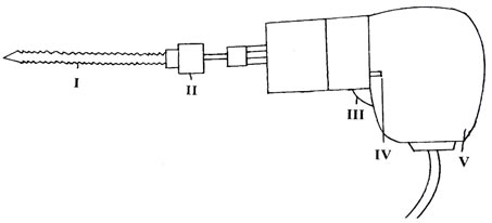
(b) The diagram below illustrates a major equipment used in an electrical workshop. Study the diagram and answer the questions that follow.

(i) Identify the equipment.
(ii) Name the parts labelled I to V.
(iii) State one function of the part labelled III.
Observation
In part (a), performance was below average as many candidates failed to get the last three operations right. Candidates response to this question shows that they were confuse.
In part (b), Most candidates labelled the part correctly. Few candidates failed the labelled part III which is trigger switch or power switch.
The expected answers include:
4 (ai)
Switch Position |
Circuit condition |
Lamp condition |
||
SW1 |
SW2 |
SW3 |
||
Up |
Up |
Up |
Close [1] |
ON [1] |
Up |
Up |
Down |
Open [1] |
OFF [1] |
Up |
Down |
Up |
Open [1] |
OFF [1] |
Up |
Down |
Down |
Close [1] |
ON [1] |
Down |
Up |
Up |
Open [1] |
OFF [1] |
Down |
Up |
Down |
Close [1] |
ON [1] |
Down |
Down |
Up |
Close [1] |
ON [1] |
(ii) One Precaution to be Taken While Carrying out Installation in 4 (a)(i)
- Ensure that all connections are mechanically sound
- Ensure that there is no exposed conducting parts
- Ensure electrical continuity
- Ensure usage of correct tools for the installation
- Observe colour coding
(bi) (Hand) drilling machine
(ii) i - drill bit
ii - chuck
iii - trigger
iv - forward and reverse switch
v - grip/handle
(iii) One Function of the Part Labelled III
The part labelled III is used for switching ON and OFF the machine
(iv) One Precaution to be Taken While Carrying out Installation in 4 (a)(i)
- Remove chuck keys from drills prior to use
- Hold tools firmly and maintain good balance
- Secure the work in a holding device not in your hands
