waecE-LEARNING
Electronics Paper 1, Nov/Dec 2011  
Questions: 1 2   Main
General Comments
Weakness/Remedies
Strength

Question 1

AIM: To demonstrate Kirchhoff’s Laws.

  1.   Connect the circuit as shown in Figure 1.
  2.   Ask the Supervisor to check the circuit connection.
  3.   Copy Table 1 into your answer booklet.

Table 1


R2(kΩ)

V1(V)

V2(V)

I1(mA)

I2 = Elecronic Image (A)

I3 = Elecronic Image (A)

V1+V2 (V)

2.2


4.7


  1.   Switch on the power supply unit.
  2.   Measure and record in Table 1 the voltages V1, V2 and current I1.
  3.   Switch off the power supply unit.
  4.   Replace R2 (2.2 kΩ) resistor with the 4.7 kΩ resistor.
  5.   Switch on the power supply unit.
  6.   Measure and record in Table 1 the corresponding values of V1, V2 and                          

current I1.

  1.   Switch off the power supply unit.
  2.   Complete Table 1.
  3.   Using the results in Table 1, verify Kirchhoff’s

  (Elecronic Image)        current law,
  (Elecronic Image        voltage law.

_____________________________________________________________________________________________________
OBSERVATION

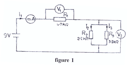
The candidates were expected to connect the circuit as shown, measure and record the current (mA) and voltages V1 and V2 (V), evaluate some quantities and verify Kirchhoff’s Current and Voltage Laws.
The expected answers were:
Table 1


R2(kΩ)

V1(V)

V2(V)

I1(mA)

I2 = Electronics Image (A)

I3 = Electronics Image (A)

V1+V2 (V)

2.2

7.021

1.979

1.501

0.899

0.599

9.000

4.7

6.367

2.625

1.361

0.558

0.795

8.992

The Chief Examiner reported that the candidates showed good knowledge of components’ connection but were inadequate in the manner the soldering was done.

Powered by Sidmach Technologies(Nigeria) Limited .
Copyright © 2015 The West African Examinations Council. All rights reserved.