Question 6
-
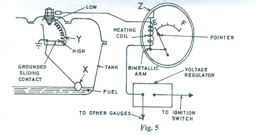
Fig. 5 is a schematic diagram of the fuel gauge of a motor vehicle.

(a) Identify the parts labelled X, Y and Z.
(b) Name the part of the vehicle where Z is located.
(c) State the function of the following in the operation of the fuel gauge in Fig. 5:
(i) bimetallic arm;
(ii) voltage regulator;
(iii) heating coil.
(d) Give one reason why the pointer is at E.
(e) State the effect of pouring more fuel into the tank on parts labelled X, Y and Z.
Observation
The candidates were expected to copy and complete the table.
(a)
X – float
Y – resistor/rheostat/variable resistor
Z – gauge unit/indicator
(b) Dashboard/panel board/instrument cluster
(c)
(i) Bimetallic arm – deflects the pointer.
(ii) Voltage regulator – stabilizes alternator output voltage/maintains
constant voltage supply to the heating coil/gauge unit/indicator.
(iii) Heating coil – increases the temperature of the bimetallic strip
(d) Reason why the pointer is at E
- The fuel left in the tank is in reserve.
- It is below what the indicator/gauge can display
- The variable resistor is at maximum/highest position
(e) Effect of more fuel in the tank on X, Y and Z
X – to rise
Y – to reduce/decrease
Z – to rise/deflect towards F
Question 6 required candidates to understand the principle of operation of the fuel gauge. It was reported that only a few candidates showed a good understanding of the principle of operation of the fuel gauge. Their performance was reported to be generally poor. More practical and hands-on experience were recommended.
