Question 1
FOUNDATION: 675 x 225 concrete strip foundation laid to a depth of 900
below ground level.
FLOOR: Earth filling.
Hardcore 300.
Concrete slab 150.
Mortar screed 25.
FIRST FLOOR: Concrete slab 150.
Mortar screed 25.
WALLS: All walls are 225 sandcrete hollow blocks walls.
BEAMS/LINTELS
AND COLUMNS: 225 x 225 reinforced concrete.
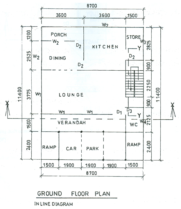
DOORS: D1 – 1200 x 2100 glazed metal door.
D2 – 900 x 2100 panel wooden door with 100 x 50 hardwood timber frame.
D3 – 750 x 2100 panel wooden door with 100 x 50 hardwood timber frame.
WINDOWS: All windows are glazed aluminium sliding type.
W1 – 1800 x 1200 (3-bays).
W2 – 1200 x 1200 (2-bays).
W3 – 1200 x 600 (2-bays).
W4 – 600x 600 (2-bays).
WARDROBE: Built with plywood and 50 x 50 hardwood timber frames.
Cloth compartment - 2100 x 600 x 2000
Box compartment - 2100 x 600 x 525
THRESHOLD STEPS: Width – 1200.
Tread – 300
Rise – 150.
ROOF: Double pitched timber roof with long span aluminium roofing sheets.
Eaves projection – 750
Pitch - 20º
Height from ground floor to ceiling – 3000
Height from first floor to ceiling - 2700


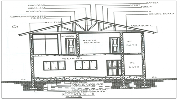
Draw to a scale of 1:50, the detailed section X – X of the building from the foundation to roof.
A good number of candidates succeeded in:
- using appropriate conventional symbols to represent the key elements of the solid ground floor construction;
- showing the walls in section withg rendering/plastering on both internal and external sides.
- identifying the timber members correctly.
Observation
However, it was observed on their drawings:
- failure to show the strip foundations in the correct proportion to the thickness of the substructural walls;
- in ability to position the doors and windows correctly, to conform with what is on the floor plan;
- failure to show the mortar screed finish specified for the concrete floor slab.
. walls in sections were not hatched;
The expected response to question 1 is as given below:

