Question 2
/e-Learning/Radio/Radio235mq2_img0001.png)
- Draw the circuit diagram of the device in Fig. 1.
- If each of the cells has an e.m.f. of 1.5 V and the bulb is rated 5 W, calculate the
- Current flowing in the circuit;
- Resistance of the circuit.
- A using the flashlight for a few hours, there was a noticeable difference in the brightness of the bulb. Suggest:
- The difference that could have been observed;
- One reason for your answer in 2(c)(i).
- To solve the problem of buying cells several times, the instructor directed the student to convert the flashlight to a rechargeable type. Complete Table 2 by giving two of the additional equipment needed and the purpose which each will serve in the new circuit.
Table 2
S/N |
Additional component |
Purpose in the new circuit |
(i) |
|
|
(ii) |
|
|
Observation
The expected responses were:
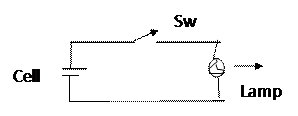
(a) Circuit diagram of the flashlight in Fig.1

(b) V = 1.5 + 1.5 = 3.0 V
P = 5 W
- Current flowing in the circuit
I = ![]() =
= ![]() = 1.67 A
= 1.67 A
- Resistance in the circuit
R= ![]() =
= ![]() = 1.80 Ω
= 1.80 Ω
Or ![]()
(c) (i) the brightness decreases | reduces | the bulb goes dim
(ii) Reasons for the Observations in 2(c)(i)
- the e.m.f. of the battery reduces
- the battery drains
- current in the circuit reduces
(d) Components needed to convert flashlight to rechargeable type
S/N |
Additional component |
Purpose in the new circuit |
(i) |
Rechargeable cells |
To ensure that charge can be stored |
(ii) |
Diode |
To convert a.c. current from the mains to d.c. which will charge the cells |
(iii) |
Capacitor |
To store charge temporarily, |
(iv) |
LED |
To indicate charging process |
(v) |
Resistor |
To limit current |
(vi) |
AC plug/socket |
To connect external grid or external supply source for recharging |
(vii) |
Transformer |
To reduce ac voltage in purpose built charger |
