Question 4
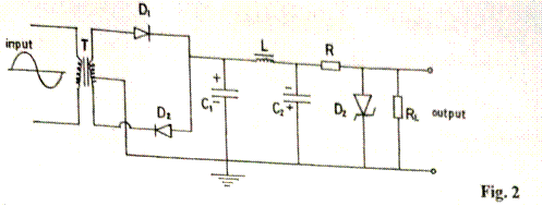
Fig. 2 is the circuit diagram of a regulated d.c. power supply unit drawn by an RTV student during a practical session.

(a). State three errors committed by the student in the circuit diagram.
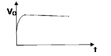
(b). Using the same components as shown in Fig. 2, sketch a correct circuit diagram with the
expected output waveform.
(c). From the diagram sketched in 4 (b), state the function of:
- D1 and D2;
- C2;
- DZ;
- L.
Observation
The Chief Examiner reported that a large percentage of the few candidates attempted question 4 did not respond well to 4(b).
The expected responses were:`
(a) Errors committed by the student in the circuit diagram
- D2 connected in the wrong | reverse direction | polarity
- C2 connected in the wrong | reverse direction | polarity
- Dz connected in the wrong | reverse direction | polarity
(b) Corrected circuit diagram with the expected output waveform
 Circuit diagram
 Output Waveform
(c) Functions of listed components
(i) D1and D2: Rectification | converts a.c. from the transformer to pulsating d.c.
(ii) C2: filtering | removing pulses from the d.c. | smoothening.
- Dz: regulation | maintaining constant output irrespective of load, RL value.
- L: filtering | combines with C1 and C2 to filter the ac ripples; it blocks the flow of ac components of current
