
Question 2
AIM: To determine the relationship between current and voltage in parallel circuit.
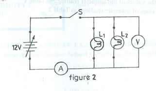
(a) Connect the circuit diagram as shown in figure two above.
(b) Ask the supervisor to check the circuit connection.
(c) Copy Table 2 into your answer booklet.
Table 2
Source voltage (V) |
Ammeter reading |
Voltmeter reading |
0 |
|
|
2 |
|
|
4 |
|
|
6 |
|
|
8 |
|
|
10 |
|
|
(d) Set the variable power supply unit to 0V.
(e) Close switch (S).
(f) Read and record in Table 2, the corresponding ammeter and voltmeter readings.
(g) Adjust the power supply unit to 2V, 4V, 6V, 8V and 10V and repeat step (f) at each setting.
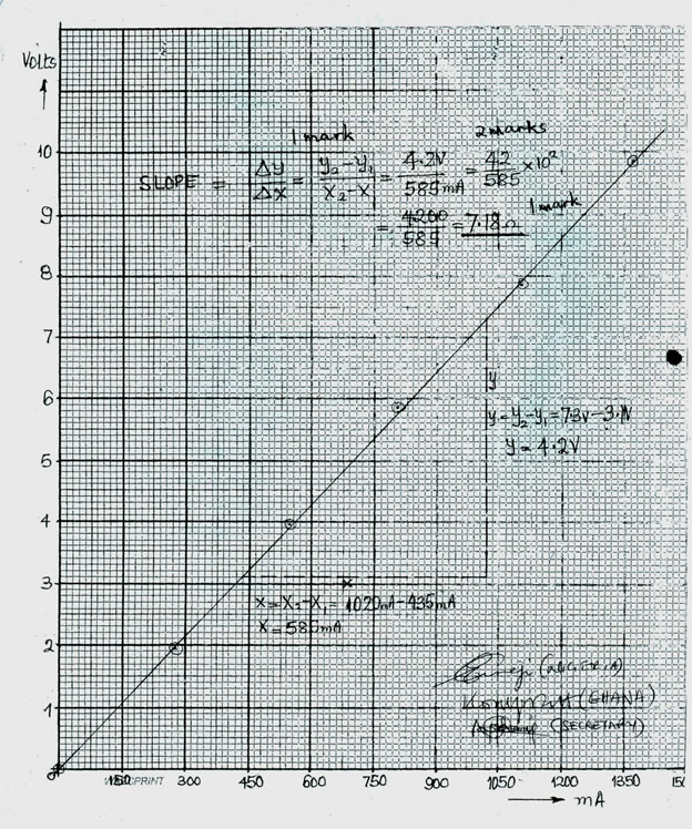
(h) Plot the graph of voltmeter readings on the vertical axis against ammeter readings on the horizontal axis.
(i) Calculate the slope of the graph.
(j) Compare the values of the ammeter readings in Table1 with values of ammeter readings in Table 2.
Observation
The expected answers were:
Table 2
Source voltage (V) |
Ammeter reading |
Voltmeter reading |
0 |
0.00 |
0.00 |
2 |
274.11 |
1.97 |
4 |
548.23 |
3.94 |
6 |
822.34 |
5.92 |
8 |
1100.00 |
7.89 |
10 |
1370.00 |
9.86 |
(a) Correct circuit connection
(b) Correct readings
(c) Correct axes (x,y and origin)
(d) Reasonable scale and title
(e) Plotting of points
(f) Line of best fit (one having scattered points very close)
(g) Slope of the graph (A linear graph)
(h) The current values in Table 2 are twice the current values in of Table 1.
The candidates were expected to determine the relationship between current and voltage in a parallel circuit.
The candidates, as reported, understood the question and carried out the task required. But some of the candidates did not record accurate voltage and current readings.