
Question 4
Fig. 3 is a diagram of an alternator circuit.
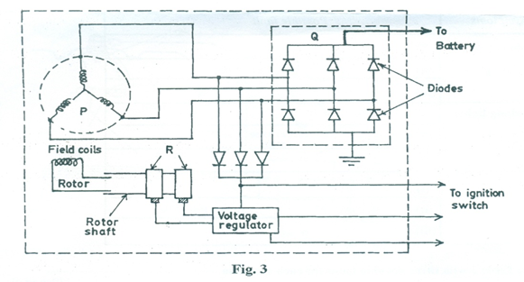
(a) Identify the parts labelled P, Q and R.
(b) State one function each of the:
(i) rotor;
(ii) diodes;
(iii) voltage regulator.
(c) State the steps involved in testing a faulty diode.
Observation
The expected answers were:
(a)
P – stator
Q – rectifier/diode assembly
R – slip rings
(b)
(i) Rotor – rotates to produce/generate electric current in the windings.
(ii) Diodes – convert alternating current to direct current.
(iii) Voltage regulator – maintain constant voltage supply/stabilizes voltage supplied.
(c) Steps involved in testing a faulty diode
- Turn off power to the circuit
- Discharge the capacitors
- Set the multitmeter to diode test mode
- Connect the leads to the diode/insert the diode leads into its provision in the meter, read and record the displayed measurement
- Reverse the test leads, read and record the displayed measurement
- If the diode is a good one, the silicon type will display 0.6-0.7V and while germanium will display 0.2-0.3V in forward bias. (Analysis of the steps)
Majority of the candidates that attempted Question 4 responded fairly well.