
Question 3
AIM: To test candidates’ knowledge of a motor vehicle lighting system
. 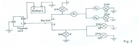
- Connect the circuit as shown in Fig. 2.
- Ask the supervisor to check the circuit connection.
- Close the switch to point Y and start the stopwatch simultaneously.
-
- Record in Table 4:
- your observation as either ON or OFF.>
- the number of flashes in 10 seconds in the column for n1.
Table 4
- your observation as either ON or OFF.>
- Repeat step (d) (ii) and record the number of flashes in the column for n2
- Repeat steps (c) and (e) for the other tests in Table 4.
- Complete Table 4 by calculating the average number of flashes.
- Compare and comment on your results in:
- tests1 and 4
- tests2 and 3.
- With all the bulbs in position, close the switch to Y and record the ammeter readings A1, A2 and A3.
- State the relationship between the ammeter readings in (i).
- Remove bulb LF read and record the ammeter readings A1, A2 and A3.
- State the relationship between the ammeter readings in (k).
- State the type of connection employed in Fig. 2.
- State one application of the circuit in Fig. 2 in a motor vehicle.
Test |
Condition of switch |
L |
R |
LF |
LR |
RF |
RR |
No. of flashes |
No. of flashes |
Avg. no. of flashes |
1. |
Switch closed to Y |
|
|
|
|
|
|
|
|
|
2. |
Switch closed to X |
|
|
|
|
|
|
|
|
|
3. |
Switch closed to X and bulb R removed |
|
|
|
|
|
|
|
|
|
4. |
Switch closed to Y and bulb LR removed |
|
|
|
|
|
|
|
|
|
Observation
Table 4
|
Condition of switch |
L |
R |
LF |
LR |
RF |
RR |
No. of flashes n1 |
No. of flashes n2 |
Avg. no of flashes |
I. |
Switch closed to Y |
ON |
OFF |
ON |
ON |
OFF |
OFF |
15 |
16 |
15/16 |
II. |
Switch closed to X |
OFF |
ON |
OFF |
OFF |
ON |
ON |
16 |
16 |
16 |
III. |
Switch closed to X and bulb R removed |
OFF |
__ |
OFF |
OFF |
ON |
ON |
16 |
16 |
16 |
IV. |
Switch closed to Y and bulb LR removed |
ON |
OFF |
ON |
__ |
OFF |
OFF |
35 |
35 |
35 |
(h) (i) The bulbs that were ON in test 4 blinked faster than those that were ON in test 1
(ii) Bulbs that were ON in test 2 blinked at the same rate as those that were ON in test 3.
(i) A1 = 3 A
A2 = 2 A
A1 = 1 A
(tolerance of + 0.2)
(l) Relationship between the ammeter readings in (i)
![]()
A1 is the sum of A2 and A3.
(k) A1 = 1.0 – 1.5 A
A2 = 0
A3 = 1.0 – 1.5 A
(m) Parallel connection
(n) Application of the circuit in Fig.2 in a motor vehicle
- To indicate intending direction of motor vehicle/Trafficator light
- To indicate that there is an hazard or emergency situation
Candidates were required to test the effect of additional load on the flashing rate of a motor vehicle flasher unit. According to
the Chief Examiners report, majority of the candidates that attempted question 2 responded well the tasks of completing the table but only
a few gave meaningful readings of ammeters 1, 2 and 3.