
Question 5
- Name the parts labelled I, II, III and IV.
- State three precautions taken while installing a PVC armoured cable.
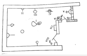
- The diagram above represents the electrical design of a living room. Identify the following electrical symbols labelled I,II,III,IV,V,VII and VIII.
- State one reason for the location of VII.
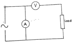
- Identify the two errors in the diagram.
- State two implications of the errors identified in 5(c)(i).
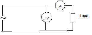
- Reproduce the diagram correctly.
- List three types of motor enclosure.
- Wall bracket against socket outlet.
- Fan against chandelier.
- Fuse board against breaker.
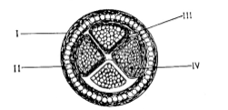
The diagram above represents a PVC armoured cable. Study it and answer the following questions.
Study the diagram and answer the following questions.
Performance was below average. Many candidates failed to identify.
Observation
The expected answers include:
-
- Armoured Cable Part
- Precautions to be taken when Installing PVC Armoured Cable
- PVC insulation must be protected against heat.
- PVC tapes should be used for insulating the conductors.
- Particular care must be taken with the cleaning and clamping of the galvanized steel wire armouring as it is often the sole earth continuity conductor/circuit protective conductor.
- The temperature of a hot pouring compound should be controlled such that it does not melt the PVC insulation of the conductor.
- Switch off/isolate the source before installation.
I - Tough PVC outer sheath
II - Steel wire armouring
III - PVC insulation
IV - Copper conductor
-
- Electrical Symbols
- Reason for Location of VII/Distribution Fuse Board
For easy access
I - ceiling fan
II - 13 A socket outlet
III - wall bracket
IV - point of light/Lamp V - 15 A socket outlet
VI - fan regulator
VII - Distribution fuse board/consumer unit
VIII - 2-way switch
-
- Errors in the Diagram
- Ammeter wrongly connected in parallel instead of series
- Voltmeter wrongly connected in series instead of parallel
- Implications of the Errors
- The instruments will not read/work
- The instruments could be damaged.
-
Types of Motor Enclosure
- Totally enclosed.
- Pipe ventilated.
- Screen proof/protected.
- Drip proof.
- Open type enclosure.
- Dust proof;
- Flame proof.
- Errors in the Diagram