
Question 1
AIM: To determine the value and stability of a transistor operating point.
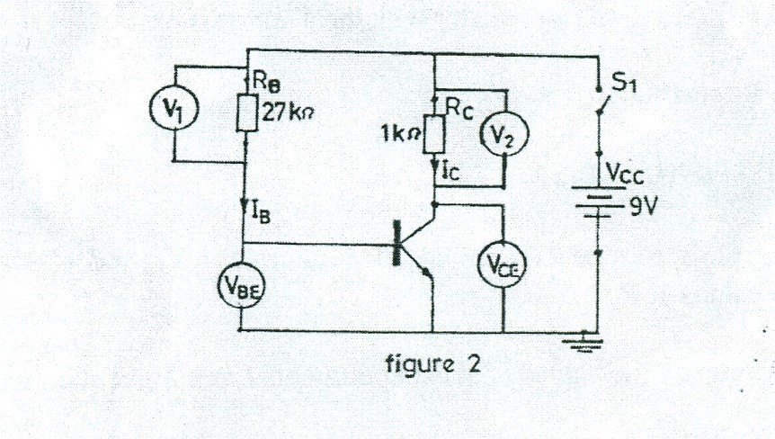
(a). Connect the circuit diagram as shown in figure 1.
(b). Ask the Supervisor to check the circuit connection.
(c). Copy Table 1 into your answer booklet.

(d). Set VBB to 3V and Vcc to 9V.
(e). Close switches S1 and S2.
(f). Measure and record in Table 1 the values of V1, V2, VBE and VCE.
(g). Open switches S1 and S2.
(h). Replace the 10kΩ resistor with 22kΩ resistor.
(i). Repeat steps (e) to (g).
(j). Repeat steps (h), (e) to (g) for the 27kΩ
(k). Complete Table 1.
(l). Briefly comment on the sets of values of VBE, VCE and β for the three values of RB.
The candidates were expected to connect the circuit as shown, measure and record the voltmeter and ammeter readings..
Observation
The expected answers were:
Table 1
RB |
V1 |
V2 |
VBE |
VCE |
IB = V1 |
IC= V2 |
β = lC/IB |
10 |
0.077 |
2.255 |
0.660 |
4.481 |
0.0077 |
2.255 |
292.86 |
22 |
0.163 |
2.171 |
0.659 |
4.651 |
0.0074 |
2.171 |
293.02 |
27 |
0.197 |
2.138 |
0.658 |
4.717 |
0.0073 |
2.138 |
293.02 |
(c) (i) VBE is approximately constant at 0.66v.
(ii) VCE increases slightly with increase in RB.
(iii) Beta β is approximately constant at 293.
The Chief Examiner reported that many candidates showed good knowledge of meter readings and the required calculations.