
Question 1
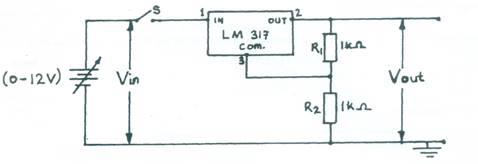
AIM: To investigate the effect of varying input voltage on the output of an LM 317 I.C voltage
regulator.
 Figure
1
Figure
1
(b) Ask the Supervisor to check the circuit connection.
(c)You are provided with Table 1.
Table 1
Vin (V) |
Vout (V) |
|
1 |
|
|
3 |
|
|
5 |
|
|
7 |
|
|
9 |
|
|
11 |
|
(d) Close switch (S) (e) Set Vin to 1V by adjusting the power supply unit.
(f) Read and record in Table 1 the corresponding value of Vout.
(g )Repeat steps (e) to (f) for the other values of Vin in Table 1.
(h) Open switch (S)
(i) Plot a graph of Vout (V) on the vertical axis against Vin (V) on the horizontal axis.
(j) From your graph, deduce the regulation voltage of the LM 317 I.C. for the circuit.
Observation
The expected responses were:
TABLE 1
VIN (V) |
VOUT (V) |
|
1 |
Any value between 0.0 and1.0 |
|
3 |
2.51 |
|
5 |
2.51 |
|
7 |
2.51 |
|
9 |
2.51 |
|
11 |
2.51 |
(i) Graph plotted using values in Table 1 with appropriate:
- choice of scale
- labelling of axes
- line of best fit
(j) Deduction (Regulation voltage = 2.5V)
Question 1 required candidates to lay out components as shown in Fig. 1, read and record the output voltage Vo while varying the input voltage. The Chief Examiner reported that only a few candidates responded well to the task.