
Question 3A
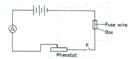
A circuit is connected as shown in the diagram above to investigate the dependence of the fusing current on the diameter of the fuse wire. The ammeter has a full scale deflection of 12 . A wire of known diameter is placed in the fuse box and the key K is closed. The rheostat is adjusted to increase the current until the wire melts thereby breaking the circuit. The Ia which melts the wire is read and recorded. The procedure is repeated with another wire of the same material and diameter, and the fusing current Ib is measured and recorded.
The mean fusing current I is determined and recorded
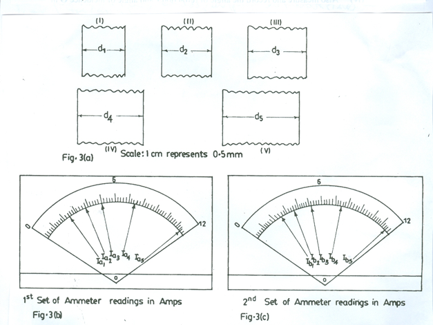
The whole experiment is repeated with four other wires of same material but different diameters. Fig. 3(a) (I - V) shows the scaled diagrams of the diameters di of the wires used while fig. 3(b) and fig.3(c) show the two sets of the ammeter readings Iaiand Ibirespectively, where i = 1, 2, 3, 4 and 5.
- Measure and record the real diameter of the wires using the given scale.
- Read and record the corresponding values of Ia and Ib.
- Evaluate I in each case.
- Also determine the corresponding values of log d and log I in each case
- Tabulate your readings
- Plot a graph with log I on the vertical axis and log d on the horizontal axis
- Determine the slope, s, of the graph.
- State two precautions that are necessary to ensure accurate results when performing this experiment.
(b) (i) From your graph, determine the diameter of the wire that would be suitable to
protect any appliance whose maximum current rating is 5.6 .
(ii) A fuse wire of length 1.0 cm and diameter 0.1 cm carries a current of 10 .
If the resistivity of the material of the wire is 5.0 x 10⁻² Ω m,calculate the
power dissipated in the wire.( = )
Observation
Part (a). This was another popular question among the candidates and it was well attempted. However, most candidates did not measure draw to the required 1 d.p. Some candidates did not convert draw using the given scale. log draw instead of log dconvert was evaluated and used to plot the graph by some candidates. Evaluation of log I was poorly handled by some candidates.
Part (b). Most candidates could not determine the diameter of the wire suitable to protect an appliance whose maximum current rating is 5.6 A. Evaluation of power dissipated in b(ii) was fairly carried out.
Candidates are expected to:
- Measure and recordfive raw values of d to at least 1d.p and
within tolerance of 0.1 cm
(ii) Convert five values of dcorrectly in mm
(iii) Read and record five values of Iacorrectly to at least 1 d.p and within
tolerance of 0.1 A
(iv) Read and recorded five valuesof Ibcorrectly to at least 1 d.p and within
tolerance of 0.1 A
- Evaluate five values of I = ½ (Ia +Ib) correctly
- Evaluate and record five values of log d correctly to at least 3 d.p
- Evaluate and recordfive values of logI correctly to at least 3 d.p
- Show composite table of at least d, Ia, Ib,I, log d and log I
- Distinguish graph axes correctly
- Chose reasonable seals
- Plot five points correctly
- Draw line of best fit.
- Evaluate slope of graph
- State any two of the following precautions:
- Ensured clean terminals/tight connections
- Avoided parallax error in reading rule/ammeter
- Noted / corrected zero error on ammeter / rule
- Key removed when not taking readings
- Repeated readings stated
b(i) log 5.6 = 0.748
0.748 shown on log I axis Corresponding value of log d shown and read on log d axis d correctly evaluated
(ii)Power = I2R OR Power =
R =
=
= 6.4 x W