
Alternative B
Question 3B
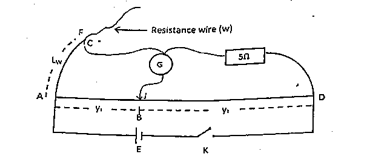
You are provided with a source of electricity of emf, E, a centre-zero galvanometer, a metre rule, a key, K, a potentiometer of wire, AD, a standard resistor R =5 Ω, a crocodile clip, C, a bare resistance wire, W, a jockey, J and connecting wires.
- Using the electrical components provided, connect the circuit as shown in the diagram leaving the circuit open.
- Connect the crocodile clip at a point, F, on the resistance wire such that AF = LW = 20.0 cm.
- Close the circuit and use the jockey to determine the balance point, B.
- Record the balance lengths, AB = and BD =
- Evaluate and .
- Repeat the procedure for four other values, and . In each case, record , and evaluate P and Q.
- Tabulate the results.
- Plot a graph with P on the vertical axis and Q on the horizontal axis.
- Calculate the slope, s, of the graph.
- What is the significance of the slope?
- State two precautions taken to ensure good results.
(b) (i) Two standard resistors A and B have resistance RA and RB respectively such that RA > RB, using the same axes of a graph, show the relationship between the voltage and current for A and B.
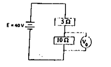
(ii) The diagram above is a potential divider circuit;
- Determine the value of V0, leaving your answer as a fraction.
- Determine the ratio of the output voltage to the input voltage.
Observation
WEAKNESSES: In question (b), most students failed because they could not show the relationship between voltage and current of resistors A and B.
STRENGTH: The majority of candidates demonstrated a strong comprehension of observations and the creation of tables of values.
EXPECTED RESPONSE:
(a) OBSERVATIONS [09]
(i) Five values of correctly recorded in cm
(Deduct ½ mark for each wrong or missing value)
(ii) Five values of correctly recorded to at least 1 d.p in cm and in trend. Trend: As Lw increases, increases. (Award ½ mark each)
(iii) Five values of correctly recorded to at least 1 d.p. in cm and
in trend. Trend: As Lw increases, decreases.
(Award ½ mark each)
- Five values of P = correctly evaluated.
(Deduct ½ mark for each wrong or missing value)
- Five values of Q = correctly evaluated.
(Deduct ½ mark for each wrong or missing value)
- Composite table showing LW, , , P and Q.
GRAPH [06]
- Both axes correctly distinguished
- Reasonable scales
- Five points correctly plotted
- Line of best fit
SLOPE02]
- Large right – angled triangle
- △log V correctly determined
- △log I correctly determined
- correctly evaluated
INTERCEPT, c, ON VERTICAL AXIS [01]
- Correctly shown
- Correctly read
CALCULATION OF P [01]
Log (100P) = c, P =
(i) Correct substitution
(ii) Correct arithmetic
ACCURACY [01]
Based on p = Resistance per unit length of metre bridge wire ± 10%
PRECAUTIONS [02]
Award 1 mark each for any two correct precautions stated in acceptable tense.
Eg:
- Ensured cleaned terminals
- Ensured tight connections
- Avoided/ noted/corrected zero error on ammeter/ voltmeter
- Avoided parallax error in taking readings on ammeter/ voltmeter
- Repeated readings shown on table
(b) (i) Increase in the external resistance leads to decrease of the current and the terminal voltage due to voltage loss across the internal resistance of the source. The voltage of the source will however remain unchanged.
(ii) R = ρ
= 7.8 x 10⁻⁸ x
= 0.099 Ω
Power = I2R
[½]
= (0.5)2 x 0.099
= 0.0248 ≈≈ 0.025 W
