
Question 2
- State Kirchhoff’s Current Law.
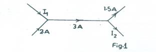
- Fig. 1 is the diagram of a current network.
Determine the value of:
- I1;
- I2.
- A transformer which converts an input of 220 V to an input of 110 V is employed in a circuit.
- State the type of the transformer employed;
- Draw a labelled schematic diagram of the transformer.
- Sketch the waveform of the output signal.
Observation
According to the Chief Examiner, majority of the candidates attempted question 2 but only a few could state Kirchhoff’s Current Law correctly and apply the law in solving question 2(b). Many candidates lost marks for not labelling the parts of the transformer correctly.The expected answers were:
- Kirchhoff’s Current Law states that the sum of currents entering a point/node/junction in a circuit is equal to the sum of currents leaving the point/node/junction.
-
-
I1 + 2 = 3A
I1 = 3 – 2A
I1 = 1 A -
3 = 1.5 + I2
I2 = 3 – 1.5A
-
I1 + 2 = 3A
-
-
Step-down transformer
-
Labelled schematic diagram of the tranformer

-
Sketch of waveform of the output signal

Sinusoidal waveform with approximately even frequency/period
-
Step-down transformer