Question 4
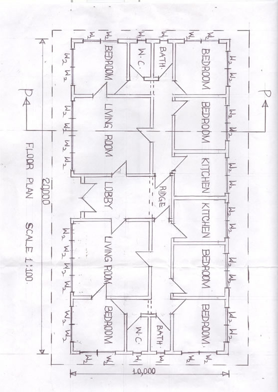
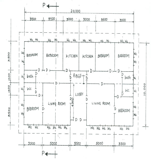
(4) The sketch below shows the floor plan of a twin three bedroom bungalow in the line diagram. Study the given specifications and answer the questions that follow:
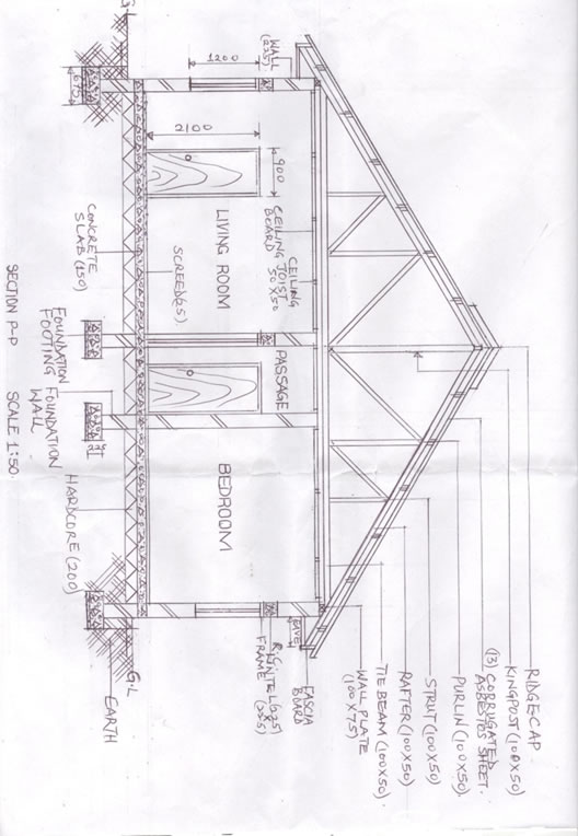
FOUNDATION: 67 x 225 concrete strip foundation at a depth 800 from ground level.
FLOOR: 200 hardcore; 150 thick concrete floor; 25 cement sand screed.
WALL: All walls are 225 hollow sandcrete blocks with 12 rendering on both sides.
LINTEL: 225 x 225 reinforced concrete.
DOOR: All doors are flush wooden. D – 2100 x 900 x 38 in 100 x 50 timber frame.
WINDOWS: All windows are sliding glazed sash in aluminium frames. W1 – 800 x 500; W2 – 1200 x 1100.
ROOF: 300 double pitch with 13 corrugated asbestos sheet; rafter – 100 x 50 at 1200 centres; purlins – 100 x 50 at 1000 centres; kingpost and strut – 100 x 50; wall plate – 100 x 75; tie beam – 100 x 50; ceiling joist – 50 x 50 at 1200 centres; floor to ceiling height 3150.
Assume suitable dimensions where necessary
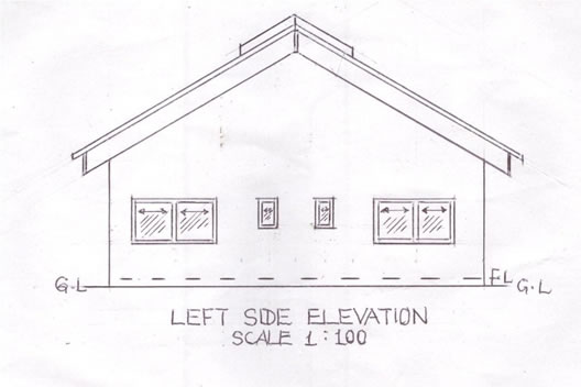
(a) Draw, to a scale of 1:100, the following views of the building:
(i) floor plan;
(ii) left side elevation.
(b) On a scale of 1:50, draw a detailed section P – P of the building.
Observation
(A) FLOOR PLAN
- draw to scale 1:100;
- draw the outline (walls);
- draw 36 windows for both flats;
- draw 22 doors for both flats;
- draw the ridge;
- draw 3 beams;
- draw the cutting plane P – P;
- identify the apartments;
- write floor plan;
- draw neatly.
(B) LEFT SIDE ELEVATION
- draw to scale;
- draw the Ground Level (GL);
- draw the floor level;
- draw 4 windows (2 big and 2 small);
- draw the roof;
- draw 3 beams;
- draw the ridge cover;
- draw the fascia board;
- draw the eaves;
- write left side elevation;
- draw neatly.
(C) SECTION P-P
- draw to scale 1:50;
- draw the ground line;
- draw four (4) foundation footings;
- draw the earth; hard core, concrete slab and screed;
- draw four (4) foundation walls with conventions ;
- draw four (4) walls in section;
- draw three (3) lintels;
- draw two (2) windows in section;
- draw one (1) door in section;
- draw two (2) flush doors in elevation;
- draw two (2) wall plates;
- draw the eaves projection and facia board;
- draw the tie beam and ceiling board;
- draw the rafter, purlins, kingpost and strut;
- draw roof cover at 30o (double pitch);
- show any six (6) labels;
- write section P – P;
- draw neatly.
FLOOR PLAN