Question 4
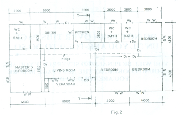
The sketch below shows the plan of a bungalow. Study the give specifications and answer the question that follows:
SPECIFICATIONS
All dimensions are given in millimetres.
FOUNDATION: 225 x 675 concrete strip foundation laid over 100 blinding at a depth of 900 below ground level.
- FLOOR: 150 hardcore, 150 concrete slab, 25 mortar screed, finish floor level to ceiling 3150.
- WALLS: All walls 225.
- LINTELS: 225 X 225 reinforced concrete.
- DOORS: All doors 2100 x 900 x 40 flush wooden in 100 x 50 timber frame except at verandah with glazed double door, 2100 x 1500 x 40 in aluminium frame.
- WINDOWS: Sliding glass in aluminium frames, bath W.C. and store windows 600 x 600, others 900 x 1200.
- BEAM: 225 x 225 reinforced concrete, 2400 above floor level.
- COLUMN: 225 X 225 reinforced concrete.
- ROOF: 25o double pitch with eaves 600 and corrugated asbestos sheets, timber rafter 1000 x 50 at 1000 centres, fascial board 25 x 250.
- Draw to a scale of 1:100 the:
- Floor plan;
- Front Elevation;
- Draw to a scale of 1:50, the sectional view on plane Y–Y.
Observation
The plan of a bungalow was given and candidates were to draw the detailed plan, front elevation and detailed section Y-Y.
Most of the candidates attempted this question and were able to draw the detailed plan and front elevation but a few of them could not draw the conve ntional symbols of window and doors properly.
Candidate’s performance was okay.Candidates were expected to do the following:
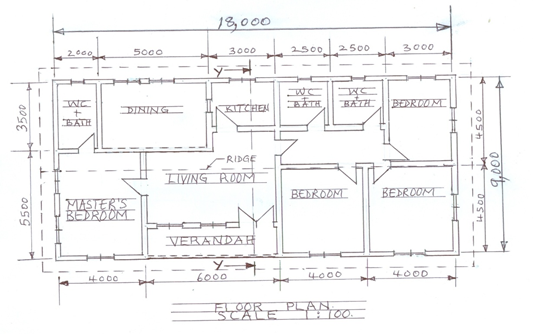
Floor plan
- draw to correct scale (1:100) (18,00* 9,000);
- draw the walls;
- draw the beams (3);
- draw the windos (30);
- draw the doors(12);
- Draw the compartment(11);
- Draw theridge cap
- draw the cutting plane Y – Y;
- draw the eaves projection;
- write floor plan.
The solution is shown below:
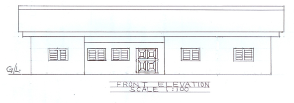
Front Elevation
- draw to corret scale;
- draw and indicate ground line;
- draw the 4 walls;
- draw 5 double windows (glass/louvre);
- draw 1 beam;
- draw fascia board;
- draw the roof;
- draw the eaves;
- write front elevation.
The solution is shown below:
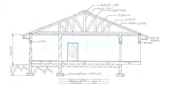
VIEW Y-Y
- draw to correct scale;
- draw the ground line;
- draw 3 foundation footings and walls with convention;
- draw the earth filling and hard core with convention;
- draw the concrete slab and floor finish with convention;
- Draw 4 walls in section; ;
- Draw 1 walls in elevation;
- Draw 2 lintels;
- Draw 1 beam;
- Draw 1 flush door and1 door in section;
- Draw 1 window in section;
- Draw the tie beam, wall plates fascia board and ceiling members;
- Draw the eaves, roof member (king post, ridge cap, rafter,purlins. Strutand roof cover);
- Identify four important parts;
- Write sectional view Y – Y.
- Neatness
The solution is shown below: