
Question 1
SECTION B
DESIGN AND DRAWING
Two sheets of drawing paper, 550 x 375 mm are provided.
Use one of the sheets of drawing paper to answer question 1 and the other sheet to answer question 2.
All dimensions are in millimeters. You should work to the main dimensions but where no dimensions are given, you should use your own discretion.
Marks will be awarded for draughtsmanship.
Answer all the questions.
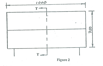
Figure 2 shows the line diagram of the front elevation of a book shelf. The depth of the book shelf is 450 mm. Use it to answer questions 1 and 2.
1. Make two preliminary freehand pictorial sketches, one each for two different designs of the book shelf.
2. Select one of the sketches in question 1 and indicate the sketch selected with a tick (![]() ). To a scale of 1:5, draw in the First angle Orthographic projection the following views:
). To a scale of 1:5, draw in the First angle Orthographic projection the following views:
(a)front elevation;
(b)sectional end elevation through TT.
Observation
Candidates’ performance in the section is generally poor. Most of the candidates do not understand the concept of design and drawing.
Candidates were expected to do the following:
Make two preliminary freehand pictorial sketches, one each for two different designs of the book shelf.
Select one of the sketches in question 1 and indicate the sketch selected with a tick (![]() ). To a scale of 1:5, draw in the First angle Orthographic projection the following views:
). To a scale of 1:5, draw in the First angle Orthographic projection the following views:
(a) front elevation;
(b) sectional end elevation through TT.
The solution is stated below:
Question 1
PICTORIAL FREE HAND SKETCHES
1. draw for resemblance;
2. draw completely;
3. draw to proportionality;
4. dimension appropriately;
5. show line quality
Question 2
- Front Elevation (FE)
- indicate the sketch selected;
- show top;
- show shelf;
- show bottom;
- show sides (2off);
- show legs (2off);
- indicate the joints (at least 2);
- dimensioning properly;
- draw scale;
- show line quality;
- name the view.
SECTIONAL END VIEW (T – T)
- indicate the cutting plane (See FE);
- show position in first angle projection;
- draw project from FE;
- draw top (in section);
- side (in elevation) ;
- draw shelf (in section);
- draw bottom (in section) ;
- draw back (in section);
- draw legs (2off);
- indicate the joints;
- dimension appropriately;
- draw scale;
- show line quality;
- name the view.