
Question 2
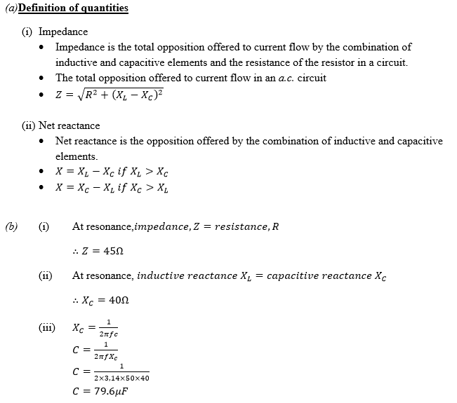
- Define the following quantities for an RLC circuit.
- Impedance
- Net reactance
- Figure 1represents the circuit diagram of an RLC circuit at resonance.
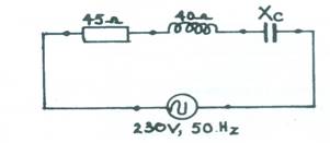 Figure 1
Determine the:
- impedance;
- reactance of the capacitor;
- capacitance of the capacitor.
OBSERVATION
According to the Chief Examiner, majority of the candidates attempted question 2 but only a few could state Kirchhoff’s Current Law correctly and apply the law in solving question 2(b). Many candidates lost marks for not labelling the parts of the transformer correctly.
The expected responses were:
According the chief examiner’s report, majority of the candidates described ‘impedance’ as ‘resistance to current flow’, which is incorrect, for resistance and impedance are two different things. The idea of a ‘net reactance’ will arise when a circuit includes both reactive and capacitive reactances. The difference between these two types will constitute net reactance which may be negative (capacitive), positive (inductive), or zero, when magnitude of capacitive and inductive reactances are the same.
b)Because the circuits is said to be at resonance, net reactance is zero; so impedance = R = 45![]() . Again resonance implies that inductive and capacitive reactances share the same magnitude; so that the reactance of the capacitor is
. Again resonance implies that inductive and capacitive reactances share the same magnitude; so that the reactance of the capacitor is ![]() , a purely imaginary quantity whose magnitude is 40 Ω. All of those who recognized the equality of magnitude did NOT recall the fact that reactance is an imaginary quantity.
, a purely imaginary quantity whose magnitude is 40 Ω. All of those who recognized the equality of magnitude did NOT recall the fact that reactance is an imaginary quantity.
Capacitance is readily computed from the foregoing expression for capacitive reactance.