
Question 1
AIM: To investigate the stabilization effect of two Zener diodes connected in parallel.
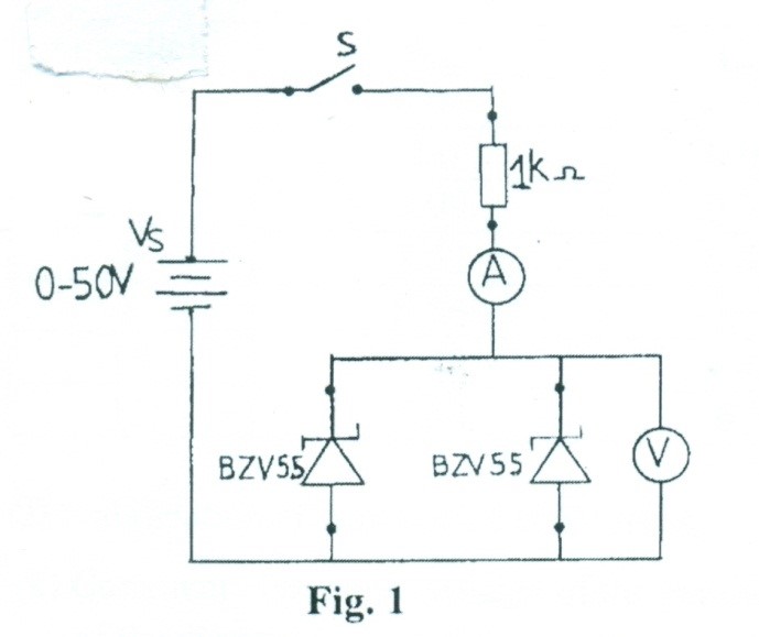
(a) Connect the circuit diagram as shown in figure 1.
(b) Ask the Supervisor to check the circuit connection.
(c) Copy Table 1 into your answer booklet.
Supply voltage |
Measured voltage |
Measured current |
0 |
|
|
2 |
|
|
4 |
|
|
6 |
|
|
8 |
|
|
10 |
|
|
12 |
|
|
(d)Close switches S1 and S2.
(e)Adjust the supply voltage (Vs) to 0V.
(f)Read and record in Table 1 the corresponding voltmeter and ammeter readings.
(g)Open switch (S).
(h)Repeat steps (d) to (g) for the other values of the voltage (Vs) in Table 1.
(i)Plot a graph of the measured voltage (V) on the vertical axis against the measured current (mA) on the horizontal axis.
(j)State the voltage at which the stabilization effect started.
(k)From the graph in step (i), briefly comment on the experiment.
The candidates were expected to connect the circuit as shown, measure and record the voltmeter readings.
Observation
The expected answers were:
Table 1
VS |
Vout |
ImA |
0 |
0.00 |
0.00 |
2 |
2.0 |
0.07 |
4 |
3.99 |
0.38 |
6 |
5.52 |
0.46 |
8 |
5.56 |
2.44 |
10 |
5.58 |
4.42 |
12 |
5.60 |
6.3 |
(J) Stabilization effects started at 6V input.
(k) Comment: The zener voltage of the parallel combination is the same as that of each
of the diodes.