
Question 2
AIM: To investigate the stabilization effect of two Zener diodes connected in series.
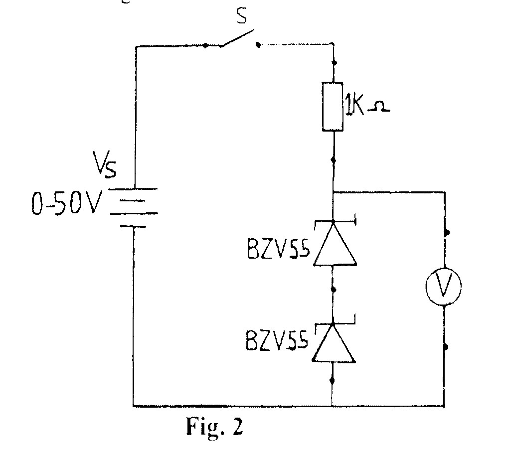 (a)Connect the circuit diagram as shown in figure 2.
(b)Ask the supervisor to check the circuit connection.
(c)Copy Table 2 into your answer booklet.
Table 2
Supply voltage |
Measured voltage |
0 |
|
4 |
|
8 |
|
12 |
|
16 |
|
20 |
|
(d) Close switch (S).
(e) Adjust the supply voltage (Vs) to 0V.
(f) Read and record in Table 2 the corresponding voltmeter reading.
(g) Open switch (S).
(h) Repeat steps (d) and (g) for the other values of (Vs) in Table 2.
(i)Plot a graph of the output voltage (V) on the vertical axis against the supply voltage (Vs) on the horizontal axis.
(j)State the voltage at which stabilization effect started.
(k)Briefly comment on the result of the experiment.
The candidates were expected to connect the circuit as shown, measure and record the values of the voltmeter readings.
Observation
The expected answers were:
Table 2
VS |
Vout |
0 |
0 |
4 |
4.44 |
8 |
7.99 |
12 |
11.106 |
16 |
11.20 |
20 |
11.22 |
(j) Stabilization effects starts at 12V
(k) Comment: The effective zener voltage of the series combination is the sum of zener
voltages of the two diodes
Many candidates used a wrong range (micro-range) in ammeter reading specified to be taken in the mille-range, hence, arriving at a wrong stabilization voltage.