
Question 2
AIM: To determine the behavior of a voltage regulator.
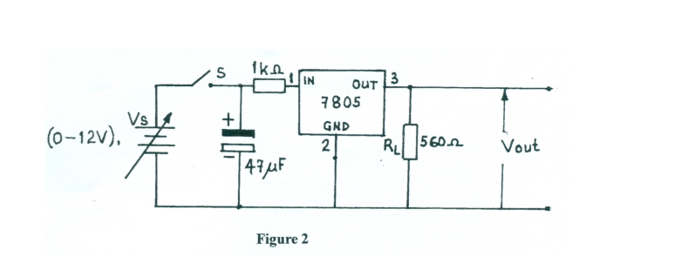
(a) Connect the circuit diagram as shown in Figure 2.
(b) Ask the supervisor to check the circuit connection.
(c) You are provided with Table 2.
Table 2
| RL (Ω) | Vout (V) |
|---|---|
| 560 Ω | |
| 1 kΩ | |
| 4.7 kΩ | |
| 10 kΩ | |
| 22 kΩ |
(d) Set the power supply unit to 12 V.
(e) Close switch (S).
(f) Read and record in Table 2, the corresponding value of Vout.
(g) Open switch (S).
(h) Replace RL (560 Ω) with the 1 kΩ resistor.
(i) Repeat steps (e) to (g) for the other values of RL in Table 2.
(j) Plot a graph of Vout on the vertical axis against RL on the horizontal axis.
(k) From your graph, state the effect of varying RL on the output voltage.
Observation
Candidates were expected to take the corresponding values (output voltage) while adjusting the voltage supply (values in Table 1) and thereafter determine the stabilization voltage of the I.C. regulator. The Chief Examiner reported that candidates responded fairly well to question 1.
The expected responses were:
TABLE 1
Table 2
| RL (Ω) | Vout (V) |
|---|---|
| 560 Ω | 5.02 |
| 1 kΩ | 5.02 |
| 4.7 kΩ | 5.00 |
| 10 kΩ | 5.00 |
| 22 kΩ | 5.00 |
(j) A linear graph with the Vout-axis value constant at 5V despite various values of RL.
(k) The output voltage remains constant as RL is varied.