
Question 3
-
AIM: To determine the operation of a transistor series regulator.
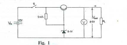
(a) Connect the circuit as shown in Fig. 1.
(b) Ask the supervisor to check the circuit connection.
(c) Copy Table 3 into your answer booklet.Table 3
RL (Ω)Vout (V)

10k
5.6k
1k
560
270
(d) Close switche S.
(k) Comment briefly on the value of the load current at which regulation ceases.
(e) Set Vin to 12V.
(f) Set the resistor RL value to 10kΩ, measure and record in Table 3 the corresponding output voltage Vout.
(g)Repeat step (f) for other values of load resistor RL inTable 3.
(h) Open switche S.
(i) Complete Table 3.
(j) Plot a graph of Vout (V) on the vertical axis against Iload (mA) on the horizontal axis.
Observation
The candidates were expected to connect the circuit as shown in Fig.1, measure and record in Table 3. They were also required to plot a graph of Vout (V) against Iload (mA) and comment briefly on it.
The expected answers were:
Table 3
RL (Ω) |
Vout(V) |
|
10k |
8.5 + 0.5 |
0.85 |
5.6k |
8.5 + 0.5 |
1.52 |
1k |
8.5+ 0.5 |
8.50 |
560 |
8.5 + 0.5 |
15.17 |
270 |
8.5 + 0.5 |
31.48 |
(j) THE GRAPH
Correct axes (x,y and origin)
Reasonable scale and title
Plotting of points
Line of best fit
(k) Comment: The regulated output remained constant over the load resistantrange.
Many candidates did well in this question as they were able to show that they are conversant with simple measuring instruments.