
Question 4
(4) Fig. 2shows the sketch plan of a bungalow. Study the sketch plan with the given
specifications and answer the questions that follow.
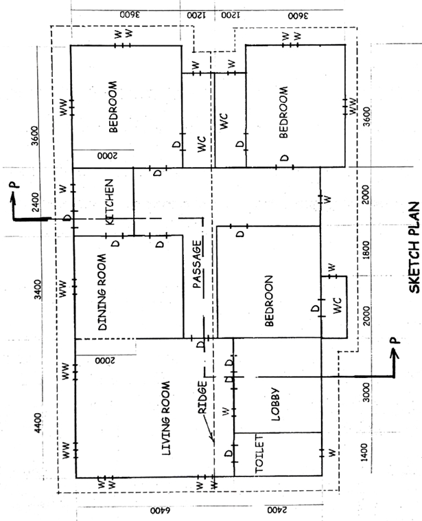
SPECIFICATIONS
All dimensions are given in millimetres.
FOUDATION: 675225 concrete strip at depth 1000 below the ground level
FLOOR: 200 hardcore;
150 thick concrete;
25cement sand screed.
WALLS: All walls 225 with 12 mortar rendering on both sides.
LINTEL: 225 225 reinforced concrete.
BEAM: 225 225 reinforced concrete 2400 abovefinishedfloor level.
COLUMN: 225 225 reinforced concrete.
DOORS: All doors flushed wooden;
D –2100 900 38 in 100 50 timber frame.
WINDOWS: W – 600 600 38;
All windows are sliding glazed sash in aluminium frames.
ROOF: Pitched gable at 30o slope with 13 corrugated asbestos sheet;
Rafter – 100 5 0 at 1000 centres;
Fascia board – 24 250;
Purlin – 100 50 1000 centres;
King post and strus – 100 50
Wall Plate – 100 75;
Tie beam – 100 50;
Ceiling Joist – 50 50 at 1200 centres;
Floor-to-ceiling height – 3100.
(a) Draw, to a scale of 1:100, the:
(i) floor plan;
(ii) front elevation.
(b) Draw, to a scale of 1:50, the detailed view of the section on plane Y–Y.
[Assume suitable dimension(s) where unspecified/necessary]
Observation
Most of the candidates answered this question and their performance was very good. However, a few of the candidates that attempted the question could not satisfactorily draw the sectional view specified in 4(b).
The solution of the poorly answered part of the question is as given.
SECTION P – P
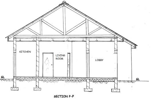
MAJOR STEPS INVOLVED IN THE DRAWING
- Drawing to correct scale (1:50)
- Drawing and indicating the ground level
- Drawing 4 foundation footings and walls with conventions (4)
- Drawing the foundation footing 1000 deep from ground level
- Drawing the earth filling, hardcore, floor slab and floor screed with
conventions - Drawing 5 walls (1 in elevation; 4 in section withconvention)
- Drawing 4 doors (2 in elevation and 2 in section with conventions)
- Drawing the lintels (2)
- Drawing 1 beam in elevation
- Drawing the roof at 30o slope
- Drawing the roof members (rafter, purlin, kingpost, struts).
- Drawing the 3 eaves projections
- Drawing the wall plate, ridge cap and asbestos sheet.
- Identifying 3 spaces
- Writing “SECTION P-P or Y-Y” beneath the drawing
- Neatness and quality of line work