
Question 2
AIM: To investigate the effect of varying the input voltage on the output of a zener diode.
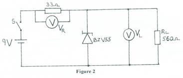
- Connect the circuit diagram as shown in Figure 2.
- Ask the supervisor to check the circuit connection.
- Copy Table2 into your answer booklet.
Table 2
RL(Ω) |
VR(V) |
VL(V) |
33 Ω |
|
|
47 Ω |
|
|
100 Ω |
|
|
470Ω |
|
|
1kΩ |
|
|
- Set the power supply unit to 9V.
- Close switch (S).
- Read and record in Table 2, voltages (VR) and (VL) .
- Open switch (S).
- Repeat steps (e) to (g) by replacing the 33Ω resistor with other values of resistors in Table 2.
- Comment on your result in Table 2.
Observation
The expected answers were;
Table 2
R(Ω) |
VR(V) |
VL(V) |
33Ω |
2.73 |
6.27 |
47 Ω |
2.75 |
6.24 |
100 Ω |
2.80 |
6.19 |
470 Ω |
4.10 |
4.89 |
1 k Ω |
5.77 |
3.23 |
(i) Comment on result
Above zener breakdown voltage, diode acts as a voltage stabilizer.
(j) To regulate voltage with varying load.
The candidates were expected to connect the circuit using the appropriate components and take readings correctly using the appropriate measuring instruments. Results of some candidates were different from the expected results because they used components which are in variance with the prescribed (or equivalent) ones in text paper.