Question 5
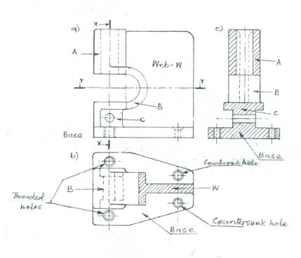
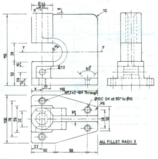
The figure below shows the three views of a machine component in first angle projection. Draw, full size, in first angle the:
(Hidden details are required on the sectional views)
Observation
Candidates were required to draw the full size of the given views of a machine. Very few candidates attempted this question and their performance was above average.
Candidates were expected to:
Front Elevation
(i) draw in first angle projection;
(ii) draw full-size;
(iii) draw the outline;
(iv) draw 3 centre lines;
(v) draw face – A;
- draw the web – W;
- draw the vertical hole in face – A (hidden);
- draw 2 – cutting planes X – X and Y – Y;
- draw face – B;
- draw FACE – C/horizontal hole;
- draw the base, threaded and countersunk holes.
Sectional Plan Y – Y
(i) draw in first angle projection;
(ii) draw full-size;
(iii) draw 6 centre lines;
(iv) draw the outline;
- draw the web – W;
- draw 2 – threaded holes/2 – countersunk holes;
- draw the base;
- draw face – B;
- section web – W;
- show hidden details.
.
Sectional End Elevation X – X
(i) draw in first angle projection;
(ii) draw full-size;
(iii) draw the outline;
(iv) draw the 4 – centre lines;
- draw face – A ;
- draw face – B;
- draw shaft – C;
- draw the base/threaded holes;
- draw the horizontal hole in face – C;
- draw the vertical hole in face – A;
- section the face – A;
- section face – C;
- section the base;
- show the web – in hidden;
- draw neatly.
The solution is shown below