Question 5

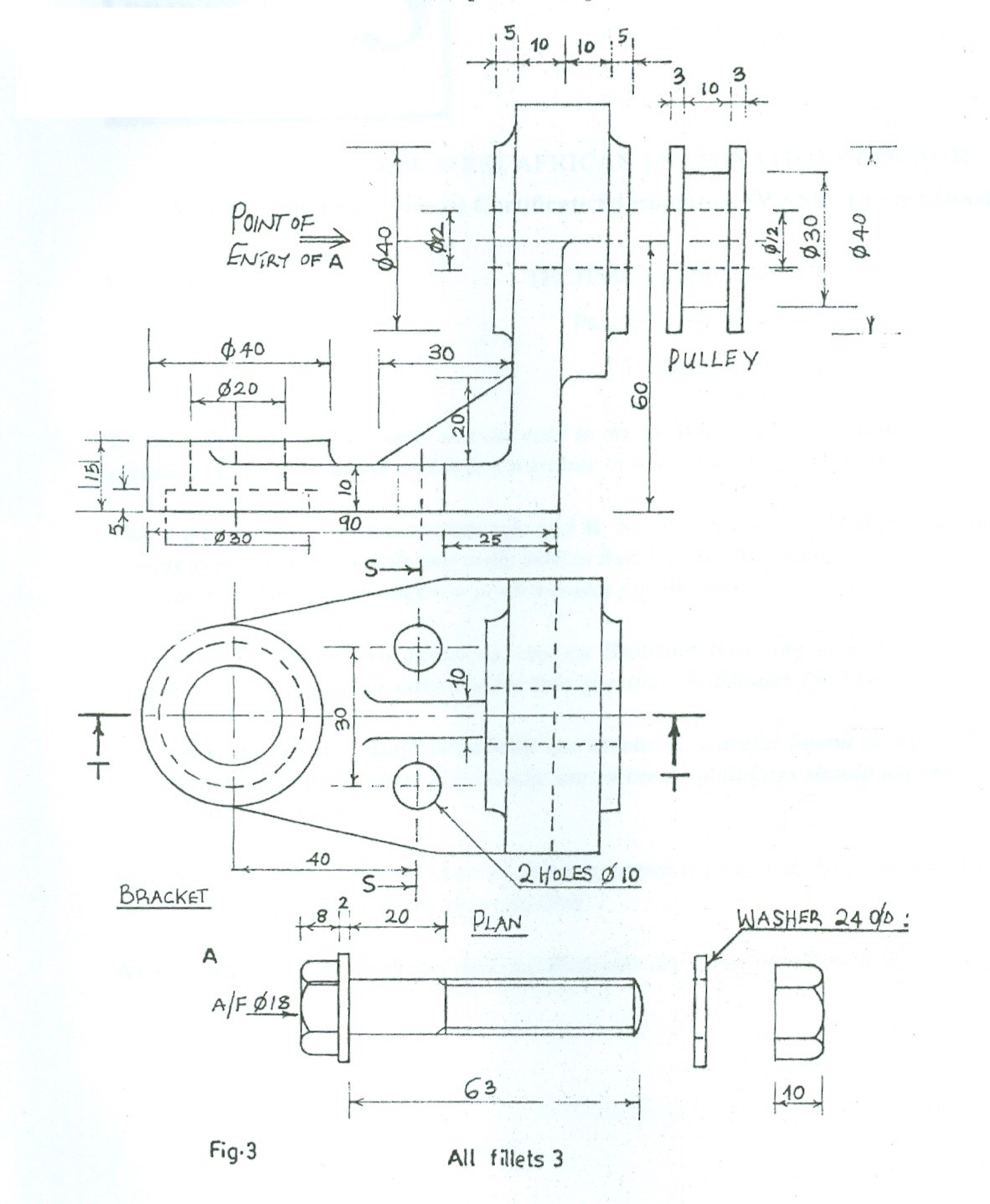
Fig. 3 shows the parts of a bevel pulley mounting bracket. With the parts assembled, draw full scale, in first angle projection the:
(a) section from elevation on cutting plane T – T;
(b) sectional end elevation on cutting plane S – S;
(c) plan.
Observation
Very few candidates attempted this question and their performance was okay. They were
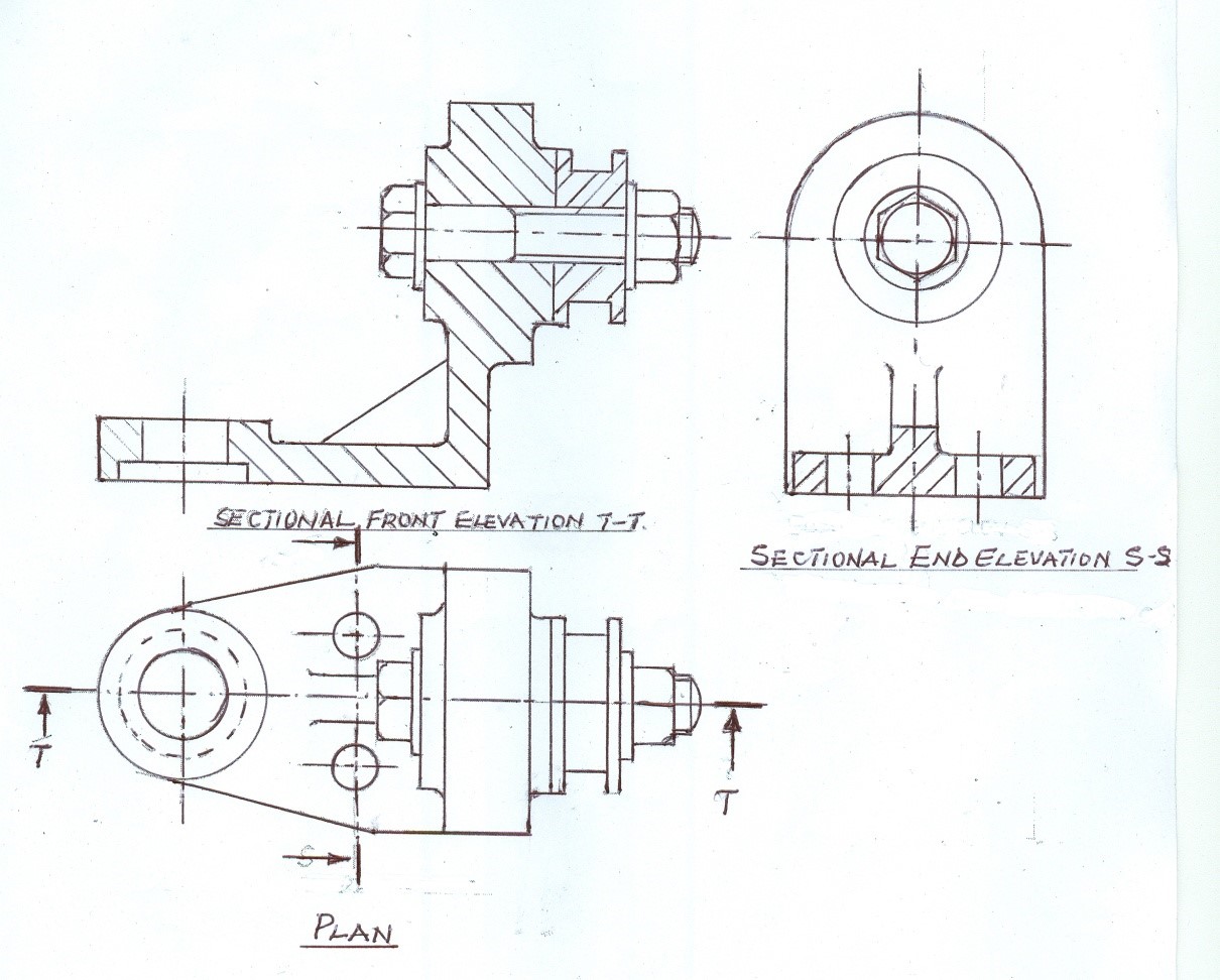
able to assemble the parts correctly on their drawing. The sectional front elevation was
correctly drawn and sectioned. The sectional end and plan were properly drawn but the
centre lines of the pulley and bolt were not properly represented.
Candidates were expected to do the following:
A SECTIONAL FRONT ELEVATION ON PLANE T – T
(i) draw in first angle projection;
(ii) draw the full size;
(iii) draw the outline;
(iv) draw two centre lines;
(v) draw the bracket;
(vi) draw the web;
(vii) draw the pulley;
(viii) draw the bolt;
(ix) draw the nut;
(x) draw the washer ;
(xi) draw the stepped hole;
(xii) draw the bracket;
(xiii) section the pulley;
(xiv) write sectional front elevation.
B. PLAN
(i) draw in first angle projection ;
(ii) draw the full size ;
(iii) draw the outline;
(iv) draw three centre lines;
- draw the bracket;
(vi) draw the bolt;
(vii) draw the washer;
(viii) draw the pulley;
(ix) draw the nut;
(x) draw the two holes ten diameter;
(xi) draw the web;
(xii) draw two cutting planes;
(xiii) write plan.
C SECTIONAL END ELEVATION S -S
(i) draw in first angle projection;
(ii) draw the full size;
(iii) draw the outline;
(iv) draw four centre lines;
(v) draw the bracket;
(vi) draw the forty diameter circle;
(vii) draw the bolt head;
(viii) draw the web;
(ix) draw two holes ten diameter;
(x) draw the section line;
(xi) write sectional end elevation S –S.
The solution is shown below:

