
Question 2
AIM: To construct and determine the frequency of an astable multivibrator.
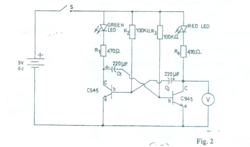
- Connect the circuit as shown in Fig. 2.
- Ask the supervisor to check the circuit connection.
- At the same time, start the stopwatch and close switch S.
[NOTE: keep the switch closed, stopwatch running and the voltmeter unadjusted throughout the experiment] - Observe the state of the red LED, read and record in Table 2 the times tstart and tend for which it is ON. [NOTE: tstart for ON state = tend for OFF/DIM state]
- While the red LED is ON, read and record in Table 2 the voltage (V).
| State of red LED | Time tstart (s) | Time tend (s) | Voltage (V) |
| ON | |||
| OFF/DIM | |||
| ON | |||
| OFF/DIM | |||
| ON | |||
| OFF/DIM |
Observation
The Chief Examiner reported that question 2 was a bit more involving as candidates were required to take the readings of the voltmeter at specific times to ensure accuracy. It was further reported that majority of the candidates that attempted the question responded very well ranging from the values obtained to the shape of the graph.
The expected answers were:
Table 2
State of red LED |
Time tstart (s) |
Time tend (s) |
Voltage (V) |
ON |
0 |
16 |
0.14 |
OFF/DIM |
16 |
30 |
7.33 |
ON |
30 |
50 |
0.13 |
OFF/DIM |
50 |
65 |
7.30 |
ON |
65 |
85 |
0.14 |
OFF/DIM |
85 |
100 |
7.28 |
VON - values between 0 and 0.3V
VOFF - values between 7 and 9.5V
tstart(s) - time difference (tend-tstart )of between 14 and 30
tend(s) - time difference (tend-tstart )of between 14 and 30 seconds.
(j) Rectangular/square-wave graph with appropriate:
- title;
- choice of scales;
- plotting of points;
- joining of points;
- labelling of axes.
(m) Applications of the circuit in Fig. 2 in a radio receiver
- Tuning circuit
- Digital radio tuner
- Keyed ON/OFF signal
- Digital transmission
- Clocking signal/Generation of square waves.
- Power supply(SMPS)
- Inverter