Question 4
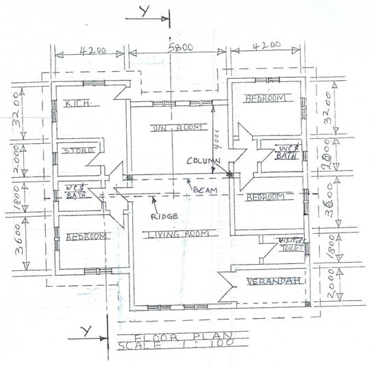
The sketch below shows the plan of a bungalow. Study the given specifications and answer the question that follow:
SPECIFICATIONS
All dimensions are given in millimetres.
FOUNDATION: 225 x 675 concrete strip foundation laid over 100 blinding at a depth of 900 below ground level.
FLOOR: 150 hardcore, 150 concrete slab, 25 mortar screed, finish floor level to ceiling 3150.
WALLS: All walls 225.
LINTEL: 225 X 225 reinforced concrete.
DOORS: All doors 2100 x 900 x 40 flush wooden in 100 x 50 timber frame except at verandah with glazed double door, 2100 x 1500 x 40 in aluminium frame.
WINDOWS: Sliding glass in aluminium frames, bath W.C. and store windows 600 x 600, others 900 x 1200.
BEAM: 225 x 225 reinforced concrete, 2400 above floor level.
COLUMN: 225 X 225 reinforced concrete.
ROOF: 25o double pitch with eaves 600 and corrugated asbestos sheets, timber rafter 1000 x 50 at 1000 centres, fascia board 25 x 250.
(a) Draw to a scale of 1:100 the:
(i) floor plan;
- front elevation.
(b) Draw to a scale of 1:50, the sectional view on plane Y–Y.
Observation
This question is optional, candidates were expected to attempt the Building Drawing or Mechanical Drawing.
Candidates who attempted the Building drawing were expected to draw to scale 1:100 the floor plane and the front elevation of the given bungalow.
Also candidates were required to draw to scale of 1:50, the sectional view on plane
Y – Y.
Most of the candidates attempted this question and their performance was impressive except for some who could not draw sectional view properly.
Candidates were expected to do the following:
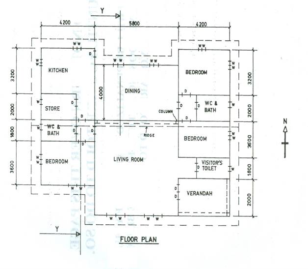
Floor plan
- draw to correct scale (1:100);
- draw the walls;
- draw the columns (3);
iv. draw the beams (3);
v. draw the windows (26);
vi. draw the doors(13);
vii. draw the cutting plane Y – Y;
- draw the eaves projection;
- label the spaces (14);
- write the floor plan.
The solution is shown below:
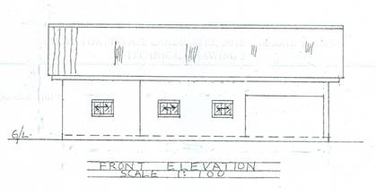
Front elevation
- draw to scale;
- draw and indicate ground line (G/L);
- draw the floor level;
- draw 3 double sliding windows with convention;
- draw 1 column;
- draw 1 beam;
- draw 3 walls;
- draw the roof;
- draw the eaves;
- write front elevation.
The solution is shown below:
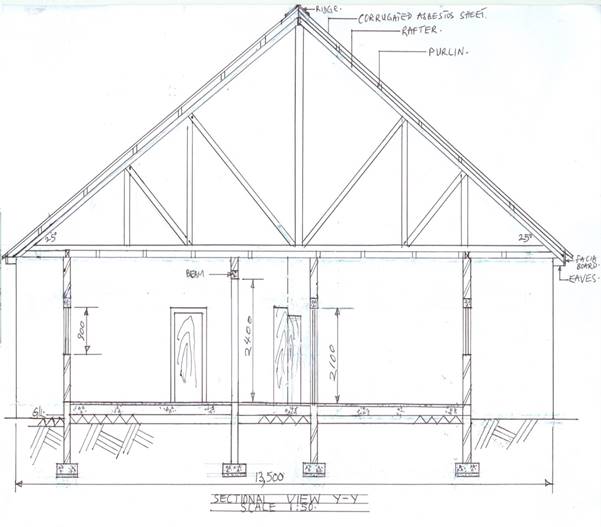
Sectional view Y - Y
- draw to correct scale (1:50);
- draw the ground line;
- draw 4 foundation footings with convention;
- draw the earth filling with convention;
- draw the hardcore with convention;
- draw the concrete slab with convention;
- draw the floor finish;
- draw 4 walls in section;
- draw 1 column;
- draw 2 walls in elevation;
- draw 3 lintels;
- draw 1 beam;
- draw 2 windows in section;
- draw 2 doors (1 in elev. & 1 in sect.);
- draw 2 half doors in elevation;
- draw 25o double pitch roof to include roof members
(rafter, purlin, ridge, roofing sheet);
xvii. draw the ceiling members(joist,nogging and ceiling);
xviii. draw the eaves and fascia boards ;
xix. write sectional view Y – Y.
The solution is shown below: