Question 4
FOUDATION: 675 x 225 concrete strip foundation on 15 blinding at1000 from ground level.
FLOOR: 200 hardcore, 150 concrete slab, 225 terazzo floor finish;
Floor level is 450 higher than ground level;
Height of floor to ceiling 3100.
STEPS: Riser 150, tread 220.
WALLS: All walls 225 with 12 ceramic tiles wall finish;
DOORS: All doors glazed, three panel in 225 x 50 timber frame.
D. - 2100 x 900 x 38
D.D - 2100 x 1800 x 38
WINDOWS: W – 2000 x 1200 sliding glazed in aluminium frame.
W1 – 900 x 600 top hung casement window, glazed in
aluminium frame.
LINTEL: 225 X 225 reinforced concrete at 210 above floor level.
BEAM: 2 Nos. 225 x 225 reinforced concrete at 2,350 above floor level.
ROOF: 350 double pitch;
100 x 50 rafters;
100 x 50 purlins;
100 x 50 struts;
100 x 75 wall plate;
50 x 50 ceiling noggins at 600 centre to centre;
30 x 185 ridge cap;
28 fascia board;
18 soffit board;
900 ves projection.
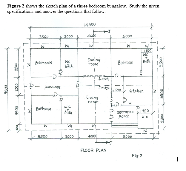
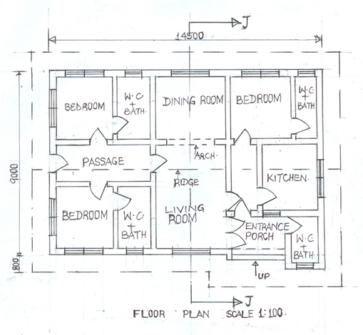
(a) Draw to a scale of 1: 100, the
(i) floor plan;
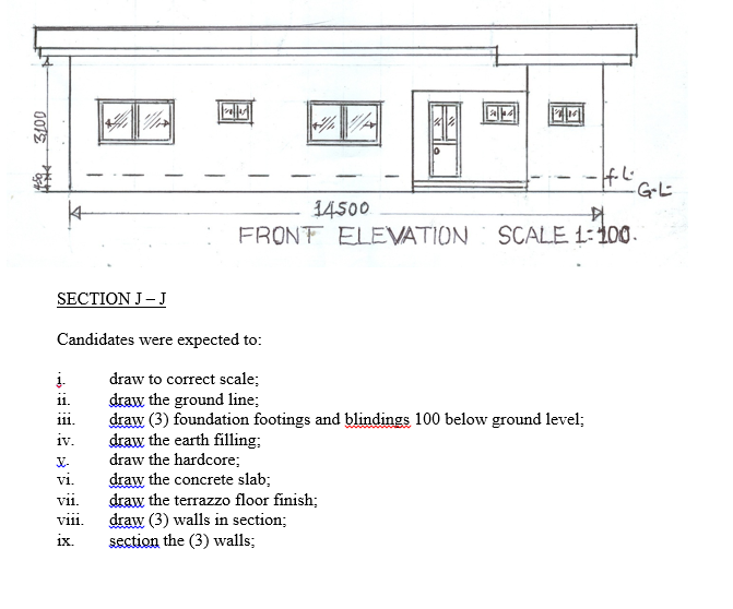
(ii) front elevation.
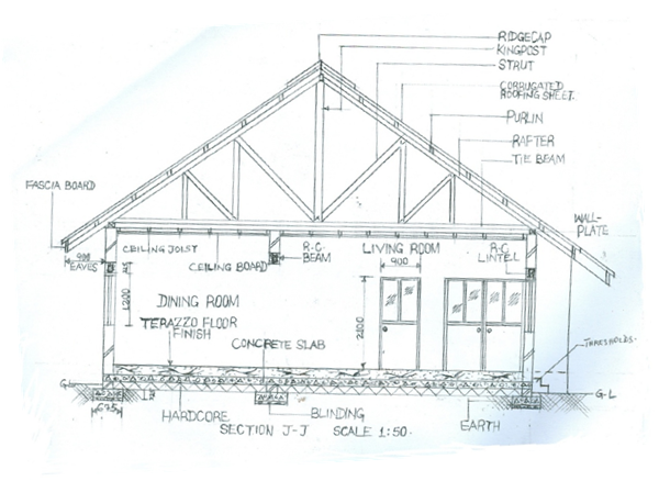
(b) Draw to a scale of 1:50, the sectional view of J – J.
Observation
The candidates were required to draw the floor plan, front elevation to scale 1: 100 and sectional elevation of the building to scale 1:50 looking at the building from the direction of view.
Most of the candidates attempted this question. They were able to draw the floor plan and elevation satisfactorily but could not do much on the sectional view. Also, some of the candidates could not interpret the drawing effectively and some did not draw to the scale given.
Candidates were expected to:
FLOOR PLAN
i. draw to scale 1:100;
ii. draw the walls;
iii. draw (13) windows;
iv. draw (14) doors;
v. draw the arch;
vi. draw the ridge cap;
vii. draw the eaves projection;
viii. draw the cutting plane J-J;
ix. identify (12) apartments;
x. write floor plan.
The solution is shown below:
FRONT ELEVATION
Candidates were expected to:
i. draw to correct scale 1:100;
ii. draw the ground line (G.L);
iii. draw the floor level;
iv. draw (2) double sliding windows;
v. draw (3) single sliding windows;
vi. draw (1) single door;
vii. draw (4) vertical walls;
viii. draw the fascia board and eaves projection;
ix. draw the beam;
x. draw the roof;
xi. write front elevation.
The solution is shown below:
x. draw wall in elevation;
xi. draw (2) lintels and beam;
xii. draw (2) windows in section;
xiii. draw (2) doors in elevation;
xiv. draw the thresholds;
xv. draw (2) fascia boards;
xvi. draw (2) eaves projections;
xvii. draw five roof members (struts, kingpost, purlin, rafter, roof cover and ridge cap;)
xviii. draw the (2) wall plates;
xix. draw ceiling and noggings;
xx. write section J – J.
The solution is shown below: