
Question 5
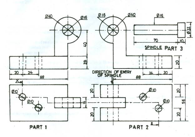
The figure below shows parts of a door hinge. Part 1 fits into part 2 and are held in position by the spindle in part 3.
Draw, full size, the assembly in first angle projection, the following:
- front elevation;
- plan;
- section X-X.
Observation
Candidates were asked to draw front elevation, plan and section of the given door hinge.
Very few candidates attempted this question, their performance was satisfactory.
Candidates were expected to do the following:
(A) FRONT ELEVATION
- draw in first angle projection;
- draw full size;
- draw the outline;
- draw (6) centres lines;
- draw the correct assembly;
- draw part 1 in position;
- draw part 2 in position;
- draw spindle-part 3 in position;
- draw the 4 holes;
- write front elevation.
(B) PLAN
- draw in first angle projection;
- draw full size;
- draw the correct assembly;
- draw the outline;
- draw (6) centres lines;
- draw part 1 in position;
- draw part 2 in position;
- draw the spindle-part 3 in position;
- draw the 4 holes;
- draw the cutting plane;
- write front elevation.
(C) SECTION X-X
- draw in first angle projection;
- draw full size;
- draw the correct assembly;
- draw the outline;
- draw (3) centres lines;
- draw the spindle;
- draw face-J;
- draw the base;
- draw the 2 holes;
- write section X-X.
The solution is shown below:
